VCC-X Operator Interface SD
SYSTEM CONNECTION
7
Modular System Manager SD Network Connection
Network Connection
As previously described, when you are connecting the Modular
System Manager to a Networked System, the Modular System
Manager is connected to the communications and power loop of
the system via modular cables. These cables simply plug into the
System Manager board and to any device with modular connectors
on any local loop on the system. Devices with modular connectors
include the Power/Comm Distribution Board, VAV/Zone controller,
and MiniLink Polling Device. By using these plug-in connections,
wiring errors are virtually eliminated and system installation is fast
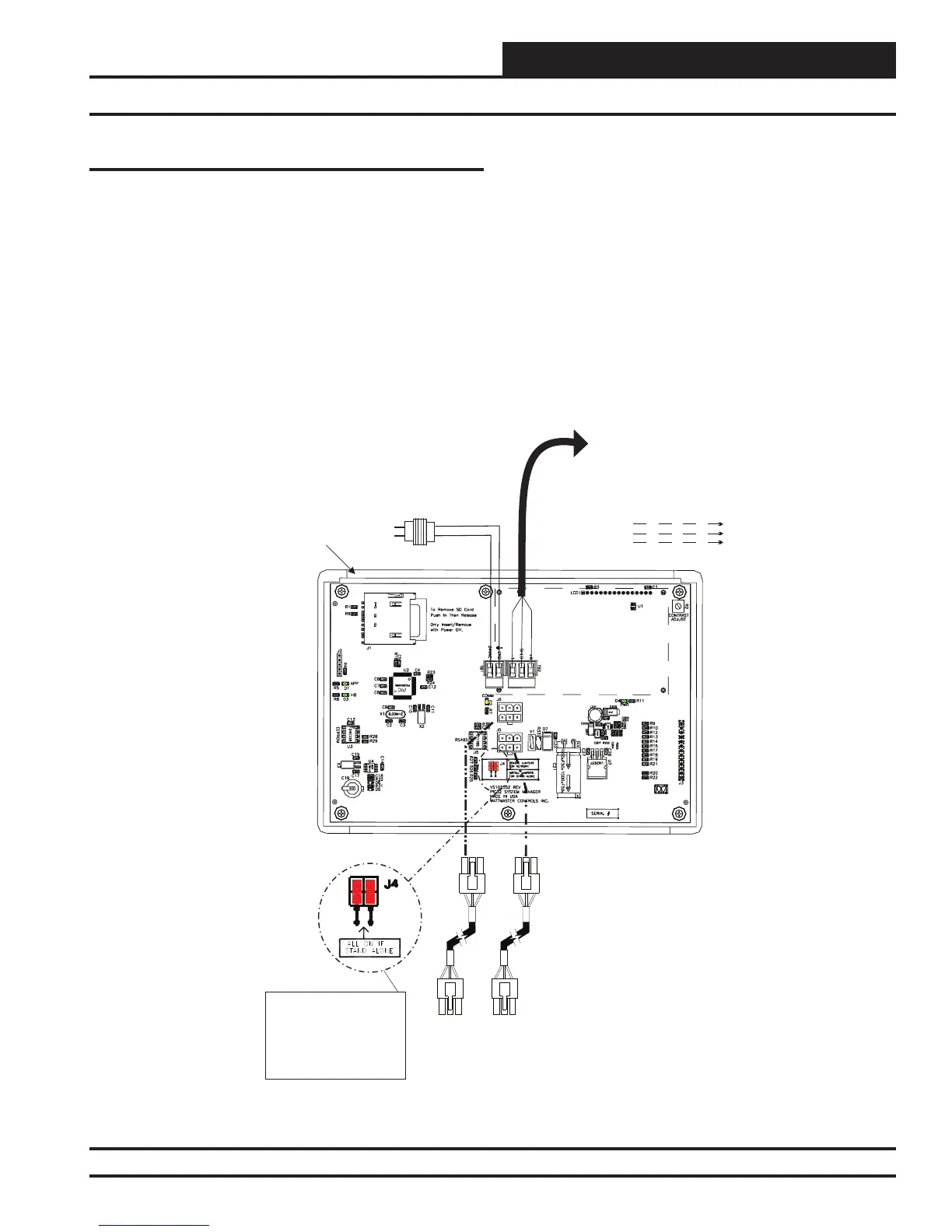
and easy. See Figure 4 below for typical connection information.
See Figure 5 on page 8 for typical Power/Comm board wiring and
connection information.
Figure 4: Modular System Manager SD - Network
When the System Manager is to be connected to a Stand Alone
system, a 12-foot cable with modular connectors on one end and
stripped wire ends on the other end is provided for this purpose. This
is used to facilitate connecting communications and power wiring
to the Modular System Manager from a 24 VAC power source and
to the HVAC unit controller communication wiring terminals. See
Figure 6 on page 9 for wiring details. If the supplied cable wire is
not long enough for your installation, a standard modular cable of
the correct length can be purchased through WattMaster and one of
the modular connectors can be cut off to allow for the transformer
and communication terminal wiring connections. It is recommended
that you do not splice the communications wire if at all possible.
The transformer should be rated at 6 VA minimum power output.
All Modular Power/Comm
Cables Are To Be
WattMaster Part Number
PCC-xx Or PCCE-xx
Cables.
Power/Comm Cables To
Power/Comm
Or VAV/Zone Controllers On
Local Loop.
Distribution
Board, MiniLink Polling Device
Modular System
Manager SD
Back View
NOTE: For Stand-Alone
Installations (No CommLink
or MiniLink), All TERM
Jumpers Must Be ON.
For All Applications With
CommLink(s) Or MiniLink(s),
All Jumpers Must Be OFF.
4
GB
If Desired, Instead Of Using A
Power/Comm Cable, You Can Use 2
Conductor Twisted Pair With Shield
Cable To Connect To The Power/
Comm Board.
R
SH
T
R
SH
T
R
SH
T
R
SH
T
All Comm Loop Wiring Is
Straight Thru
Local Loop RS-485
9600 Baud
Line
24VAC
24VAC Transformer
(By Others)
Rated for 6 VA
GND