26VCCX-454 Controller Technical Guide
WIRING
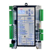
12 Relay E-BUS Expansion Module
The ASM01873 12 Relay E-BUS Expansion Module provides 12
dry contact congurable relay outputs. See Figure 17, this page,
for complete wiring details.
The 12 Relay E-BUS Expansion Module can be used in conjunction
with the EM1 Expansion Module. The expansion modules can be
used individually or together to provide the required inputs and
outputs for the specic applications.
WARNING: Observe polarity! All boards must be wired
with GND-to-GND and 24 VAC-to-24
VAC. Failure to observe polarity will result
in damage to one or more of the boards.
Expansion modules must be wired in such
a way that the expansion modules and the
controller are always powered together. Loss
of power to the expansion module will cause
the controller to become inoperative until
power is restored to the expansion module.
12 Relay E-BUS
Expansion Module
E-BUS cable connects to
E-BUS cable connects to
the next Expansion Board
Controller
Figure 17: 12 Relay E-BUS Expansion Module Wiring