28VCCX-454 Controller Technical Guide
START-UP AND COMMISSIONING
Powering Up and Conguration
Before Applying Power
In order to have a trouble free start-up, it is important to follow a
few simple procedures. Before applying power for the rst time, it
is very important to run through a few simple checks.
Power Wiring
One of the most important checks to make before powering up the
system for the rst time is to conrm proper voltage and transformer
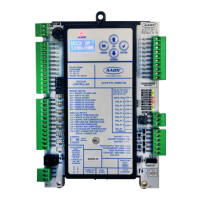
sizing for each controller. Each VCCX-454 Controller requires 15
VA of power delivered to it at 24 VAC. Use separate transformers
for each device (preferred) or power several devices from a common
transformer.
WARNING: Observe polarity! All boards must be wired
with GND-to-GND and 24 VAC-to-24 VAC.
Failure to observe polarity will result in
damage to one or more of the boards.
Check all wiring leads at the terminal block for tightness. Be sure
that wire strands do not stick out and touch adjacent terminals.
Conrm all sensors required for the system are mounted in the
appropriate location and wired into the correct terminals on the
VCCX-454 Controller.
After all the above wiring checks are complete, apply power to the
VCCX-454 Controller.
Conguring the Controller
The next step is conguring the controller for specic requirements.
In order to congure the VCCX-454 Controller, use an operator
interface. This controller is congured only through Prism II
NOTE: Use Prism II to congure units with RM-454-D,
RM-454-V and RM-454-Z modules.
No matter which operator interface is used, AAON recommends
proceeding with the programming and setup of the VCCX-454
Controller in the order that follows:
Congure the controller for the application.
1. Program the controller setpoints.
2. Program the controller operation schedules.
3. Set the controller current time and date.
4. Review the controller status screens to verify system
operation and correct controller conguration.
NOTE: For BACnet Conguration, see Appendix C.