31VCCX-454 Controller Technical Guide
INPUTS AND OUTPUTS
A2L Mitigation Controller Inputs/Outputs Maps
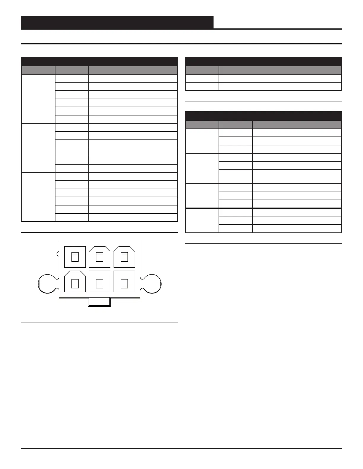
ANALOG INPUTS
SENSOR # PIN NAME
1 1 Power (+12VDC)
2 Signal In
3 Not Used
4 Not Used
5 Signal Out
6 GND
2 1 Power (+12VDC)
2 Signal In
3 Not Used
4 Not Used
5 Signal Out
6 GND
3 1 Power (+12VDC)
2 Signal In
3 Not Used
4 Not Used
5 Signal Out
6 GND
Table 10: Analog Inputs Wiring
1 2 3
4 5 6
Figure 19: Analog Input Pin Diagram
BINARY INPUTS
INPUT NAME
BIN1 Fan Proof of Flow
EXT1 Fan 24V
Table 11: Binary Inputs Wiring
RELAY INPUTS
NAME PIN NAME
FAN NC Fan - Normal condition held open
COMM Common
NO Not Available
COMP NC Not Available
COMM Common
NO Compressor - Normal condition held
closed
ALARM NC Not Available
COMM Common
NO Alarm - Normal condition held closed
VAV NC VAV - Normal condition held open
COMM Common
NO VAV - Normal condition held closed
Table 12: Relay Inputs Wiring