Interfaces and Connectible Terminals U
pn
Ports
47
*) If the DIP switches are set accordingly, the conductors of the adjacent U
pn
port
will be connected here; use only the first U
pn
port in this configuration.
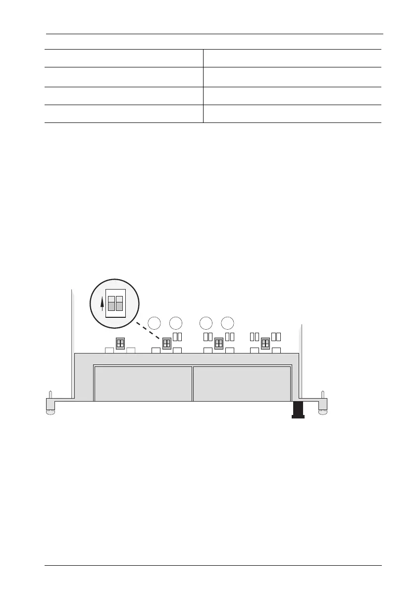
Setting DIP Switches
1. Remove the interface card by following the instructions in Installing Interface
Cards starting on page 31.
2. The DIP switches are protected by a plastic foil. Use a pointed tool such as a
screwdriver to slide the DIP switches to the right (see arrow in the illustration
Location of the DIP switches on the MS+UPN2-8 interface card on page 47).
Location of the DIP switches on the MS+UPN2-8 interface card
6U
pn
b *)
7Not used
8Not used
Pin Number Assignment
1
2
ON