2600T Series Pressure transmitters 266 models | SOI/266-XC 5
Hazardous Area Considerations
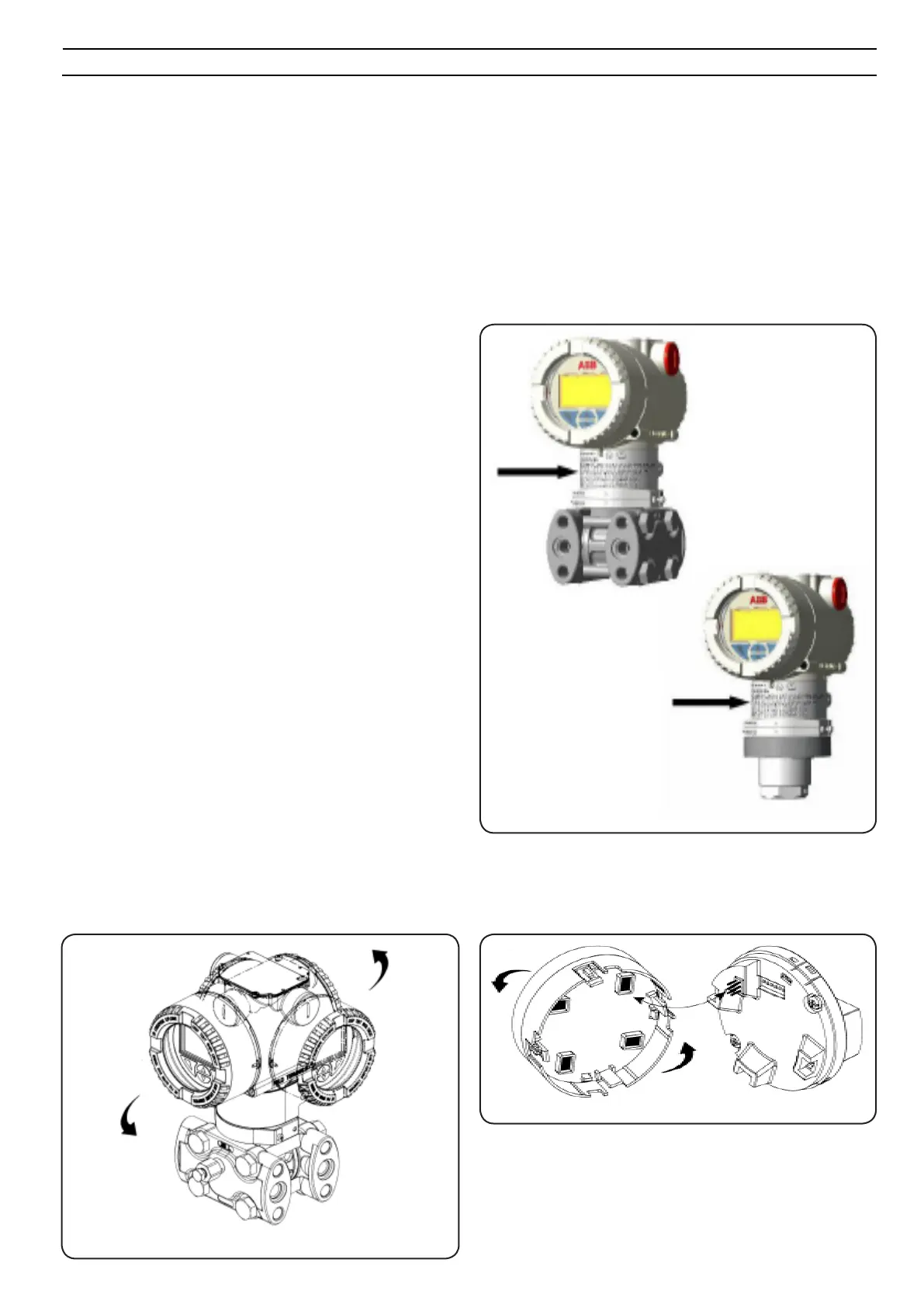
The transmitter must be installed in hazardous area only if it is properly certied. The certication plate is permanently xed on the
side of the transmitter top housing (as shown by the gure).
The 266 Pressure Transmitter Line can have the following certications:
Transmitter
The transmitter can be anged directly to the shut-off valve. A mounting bracket for wall or pipe mounting (2" pipe) available as an
accessory.
Mount the transmitter in such a way that the process ange axes are vertical (horizontal in case of barrel-type aluminum housing) in
order to avoid zero shifts. If the transmitter is installed at an incline, the hydrostatic pressure of the lling uid would exert pressure
on the measuring diaphragm and thus cause a zero shift! A zero point correction would then be necessary. Pressure transmitters can
be mounted in any position.
Seal unconnected process connections on the sensor with the enclosed screw plugs (1/4-18 NPT). For this purpose, use your ofcially
approved sealing material.
ATEX INTRINSIC SAFETY
II 1 G Ex ia IIC T6 and II 1/2 G Ex ia IIC T6
II 1 D Ex iaD 20 T85°C and II 1/2 D Ex iaD 21 T85°C
ATEX EXPLOSION PROOF
II 1/2 G Ex d IIC T6 and II 1/2 D Ex tD A21 IP67 T85°C
ATEX TYPE "N" / EUROPE:
II 3 G Ex nL IIC T6 and II 3 D Ex tD A22 IP67 T85°C
COMBINED ATEX, ATEX FM and FM Canada
See detailed classications
FM Approvals US and FM Approvals Canada:
Explosionproof (US): Class I, Div. 1, Groups A, B, C, D
Explosionproof (Canada): Class I, Div. 1, Groups B, C, D
Dust ignitionproof : Class II, Div. 1, Groups E, F, G
Nonincendive: Class I, Div. 2, Groups A, B, C, D
Intrinsically safe: Class I, II, III, Div. 1, Groups A, B, C, D, E, F, G
Class I, Zone 0, AEx ia IIC T6/T4 (FM US)
Class I, Zone 0, Ex ia IIC T6/T4 (FM Canada)
IEC (Ex):
See ATEX detailed classications
INTRINSIC SAFETY/CHINA
NEPSI approval Ex ia IIC T4-T6
FLAMEPROOF/CHINA
NEPSI approval Ex d IIC T6
GOST (Russia), GOST (Kazakistan), Inmetro (Brazil)
based on ATEX.
Fig. 3 Housing rotation
Integral Display rotation
In case an optional integral display meter is installed, it is possible
to mount the display in four different positions rotated clockwise
or counterclockwise with 90° steps.
Fig. 4 Display rotation
... INSTALLATION
Housing rotation
To improve eld access to the wiring or the readability of the optional
LCD meter, the electronic housing may be rotated through 360°.
A stop prevents the housing from being turned too far.
Fig. 2 Certication plate

 Loading...


