Installing the PROFIBUS DP Interface, CI851/TP851 Section 2 Installation
112 3BSE036351-510 A
Installation of PROFIBUS DP
For installation of the fieldbus and recommended certified fieldbus devices and
components, see fieldbus documentation and Appendix C, Recommended
Components. The PROFIBUS DP must be connected with shielded twisted pair
cables.
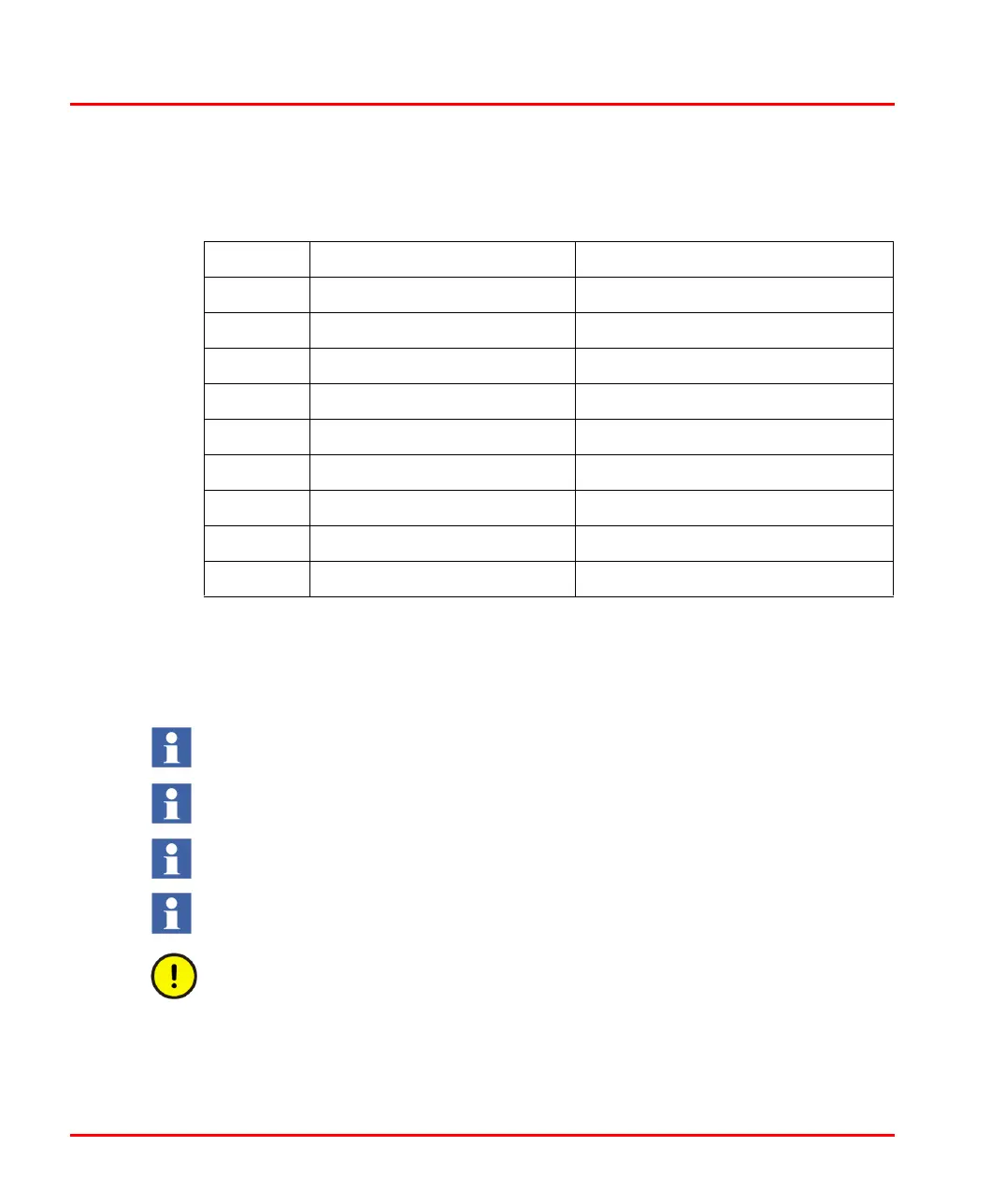
Table 12. CI851 - PROFIBUS DP Connector
PIN Designation Description
1 Shield Shield/protective ground
2 – Not Used
3 B-line Receive/Transmit Data B-line
4 RTS(TTL) Indicates direction RTS(TTL) Indicates direction
5 GND Bus GND Bus
6 +5 V Bus For terminating resistors
7 – Not used
8 A-line Receive/Transmit Data A-line
9 – Not used
For additional information on PROFIBUS DP and other suitable components,
visit the PROFIBUS User Organization web site.
Note that there is no unit redundancy for the CI851 unit.
Cannot be used in High Integrity Controller.
CI851 has been replaced by the CI854 communication interface. CI851 is only
described for legacy reasons.
It is not possible to change the CI851 unit via hot swap and it is not allowed to
perform an online upgrade of firmware in a system containing CI851.

 Loading...


