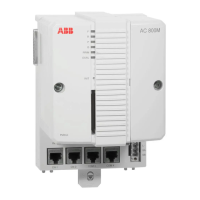
Section 2 Installation Installing the FOUNDATION Fieldbus H1 Interface, CI852/TP852
3BSE036351-510 A 113
Installing the FOUNDATION Fieldbus H1 Interface,
CI852/TP852
CI852 is powered from the processor unit via the CEX-Bus and requires therefore
no additional external power source. No field device on the FF H1 bus is powered
from the CI852.
An AC 800M Controller connected to a CI852 constitutes a FOUNDATION
Fieldbus linking device.
Use the following procedure to install the CI852/TP852:
1. Mount the unit onto the DIN-rail, see Mounting AC 800M Units onto DIN-Rail
on page 65 and Installing the PM86x/TP830 Processor Unit in Single
Configuration on page 78.
2. Install a connector on the FOUNDATION Fieldbus H1 cable. Connect the
cable screen to the ground terminal within the connector to ground the screen
via CI582.
3. Connect the FOUNDATION Fieldbus H1 cable to the contact on the baseplate.
FOUNDATION Fieldbus H1 Connection
Connect the FF H1 bus to the male DB9 connector located on the TP852 Baseplate.
The use of shielded twisted pair cables for FOUNDATION Fieldbus is
recommended (see Appendix C, Recommended Components).
Table 13. CI852 and TP852 FOUNDATION Fieldbus H1 Connector
Pin Designation Description
1–5 – Not used
6 FB-P Receive/transmit data line, positive polarity
7 FB-N Receive/transmit data line, negative polarity
8–9 – Not used

 Loading...


