Installing SM810/TP855 Section 2 Installation
104 3BSE036351-510 A
Installing SM810/TP855
The SM810 is mounted directly to the CEX-Bus on the processor unit base plate or
to the CEX-Bus interconnection unit BC810. The communication interfaces are
then mounted to the CEX-Bus on the SM810. See Figure 31 on page 100 and
Figure 32 on page 101 for configuration examples.
Digital I/O Connection
The SM810 has a connector with two digital inputs and three digital outputs that can
be used for High Integrity related digital I/O (not process I/O). See Table 10.
The input signals are used for system function, see AC 800M High Integrity
documentation.
In a redundant configuration, the corresponding digital inputs to both the
SM810’s must be connected to common digital input switches.
For example, the I2’s of both SM810’s must be connected to a common switch. If
separate sources are used, connect the sources to a common switch, and then
derive connections from the switch to both the SM810’s.
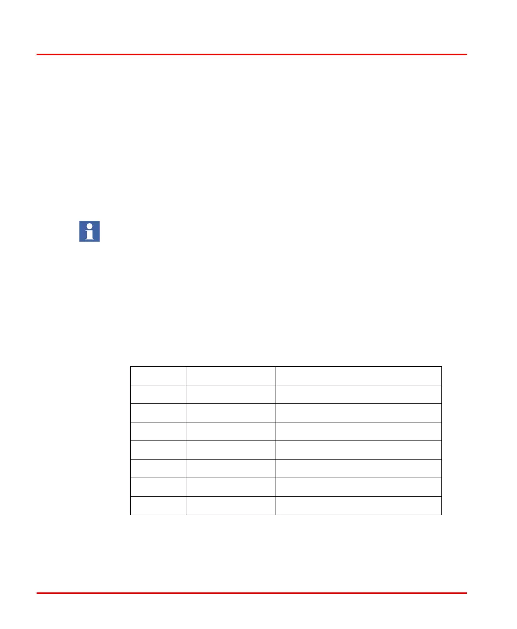
Table 10. SM810 Digital I/O Connector
PIN Designation Description
1 UP Common I/O power
2 I1 Digital input 1 (Reset all forces)
3 I2 Digital input 2 (Access enable)
4 I3 Digital input 3
5 O1 Digital output 1 (Any force active)
6 O2 Digital output 2 (System alarm)
7 ZP Common I/O return

 Loading...


