Installing the PROFIBUS DP Interface, CI854/CI854A/TP854 Section 2 Installation
118 3BSE036351-510 A
Installation of PROFIBUS DP
For installation of the fieldbus and recommended certified fieldbus devices and
components, see fieldbus documentation and Appendix C, Recommended
Components. The PROFIBUS DP must be connected with shielded twisted pair
cables.
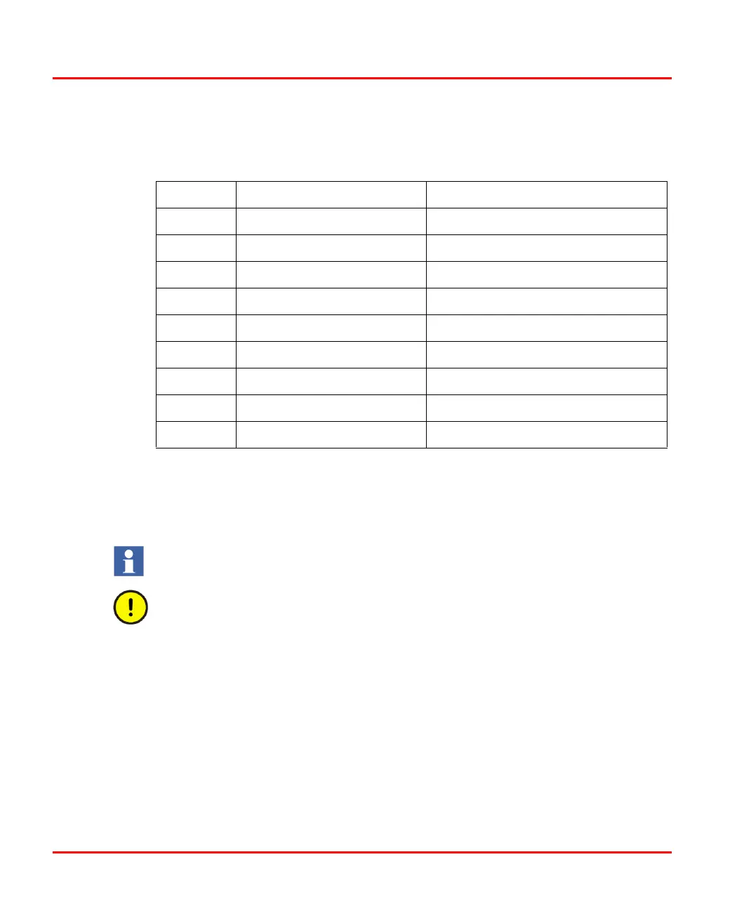
Table 15. CI854/CI854A – PROFIBUS DP Connector
PIN Designation Description
1 Shield Shield/protective ground
2 – Not Used
3 RxD/TxD-P Receive/Transmit Data P-line (B-line)
4 CNTR-P Indicates Direction to Repeater (TTL)
5 DGND Digital Ground
6 VP +5 V, for terminating resistors
7 – –
8 RxD/TxD-N Receive/Transmit Data N-line (A-line)
9 DGND Digital Ground
Note that there is no unit redundancy for the CI854 unit. Only for CI854A.
Hot swap is supported for CI854A (not CI854).

 Loading...


