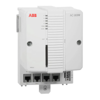
AC 800M Controller (PM8xx) Section 4 Operation
180 3BSE036351-510 A
P(ower) Green Normal state – ON
When lit, indicates that the CPU DC/DC
converter is generating valid +5 V and +3.3 V
DC supply voltages.
No software control.
B(attery) Green Normal state – ON
Lit when internal or external battery voltage is
above 3.1 V. The LED is controlled by a
software battery voltage test
(1)
.
Tx Yellow
Green
(2)
Data Transmission
(4)
,
CN1 + CN2 and COM3
(3)
+ COM4
Flashes in synchronization with Tx traffic
Rx Yellow
Green
(2)
Data Reception
(4)
,
CN1 + CN2 and COM3
(3)
+ COM4
Flashes in synchronization with Rx traffic
Valid for PM861/PM864/PM865/PM866/PM891
PRIM(ary) Yellow Lit in single and redundant configuration.
Indicates Primary CPU in redundant
configuration. Controlled by software.
DUAL Yellow Lit when the CPU is running in redundant
configuration and synchronized state.
(1) The software performs cyclic battery voltage level tests via a dedicated LED control input. The
battery provides back-up power for both the application memory and the real time clock during
power down. The battery is either accessible via the PM8xx cover panel or externally connected
to the external battery connector. Battery voltage is checked by the software. Voltage is common
for both the internal and external battery. For this reason the internal battery should be removed
when using the external battery, since having two batteries connected in parallel will result in
greatly reduced capacity.
(2) Only for PM891
(3) Not valid for PM891
(4) Only CN1 for PM851/PM851A. Do not connect to CN2.
Table 20. PM8xx – LED Indicators (Continued)
Marking Color Function

 Loading...


