NOTICE!
Risk of damaging the PLC modules!
Overvoltages and short circuits might damage the PLC modules.
– Make sure that all voltage sources (supply voltage and process supply
voltage) are switched off before you begin with operations at the system.
– Never connect any voltages or signals to reserved terminals (marked with
"NC"). Reserved terminals may carry internal voltages.
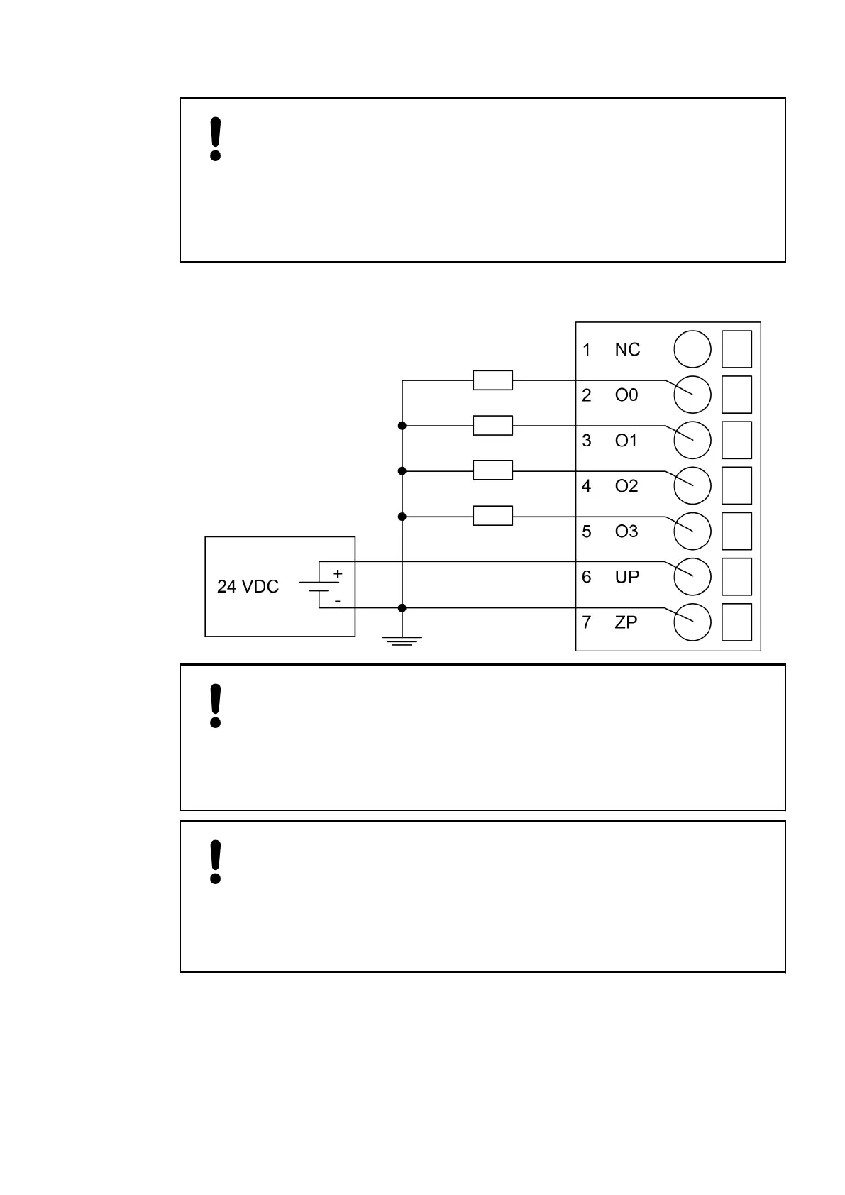
The following figure shows the electrical connection of the digital output module TA5105-4DOT:
NOTICE!
Risk of malfunctions in the plant!
Only if L+/M of the CPU is available and the outputs are already configured in
the AB program, then as soon as the UP/ZP is available, the outputs will switch
on.
This must be considered in the planning of the application.
NOTICE!
Risk of damaging the I/O module!
The outputs are not protected against short circuits and overload.
– Never short-circuit or overload the outputs.
– Never connect the outputs to other voltages.
– Use an external 3 A fast-protection fuse for the outputs.
The module provides several diagnosis functions, see Diagnosis
Ä
Chapter 6.2.2.6 “Diagnosis”
on page 113.
The meaning of the LEDs is described in the section State LEDs
Ä
Chapter 6.2.2.7 “State
LEDs” on page 114.
Option boards > TA5105-4DOT - Digital output module option board
2021/06/293ADR010635, 2, en_US112
 Loading...


