4.
The terminal blocks are not included in the scope of delivery.
The terminal blocks have to be ordered separetellly according to the CPU
type and the type of terminal blocks needed (screw or spring technology).
Insert terminal blocks for power and I/O connection to CPU, options and I/O modules.
5. Make the sensor/actuator wire connections according to the dedicated electronic module
you want to use. Provide external process power supply as required.
6. Connect a programming cable (Ethernet cable between ETH port of CPU and PC with
engineering software).
5.4 Example project
The following steps show how to set-up an application project and configure the hardware. A
simple logic is used as example to introduce in programming and commissioning of the PLC.
The workflow for creation of a visualization is explained, as well as how to set-up a webserver
for visualization.
5.4.1 Preconditions
● Automation Builder is installed and licensed as, at least, basic edition.
● AC500 V3 CPU is assembled and connected to the PC.
5.4.2 Create, set-up and save your AC500 V3 project
5.4.2.1 Create a project
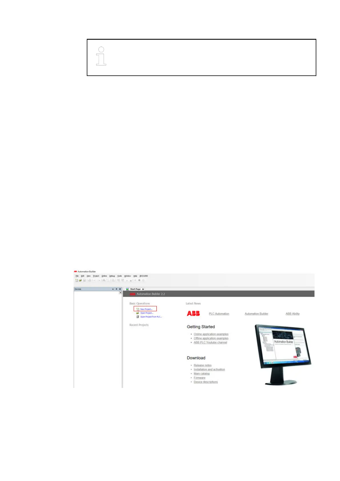
1. Launch Automation Builder either out of the desktop icon or out of the Windows menu.
2.
Select “New Project” or go to menu “File è New Project”.
Example project > Create, set-up and save your AC500 V3 project
2021/06/293ADR010635, 2, en_US22
 Loading...


