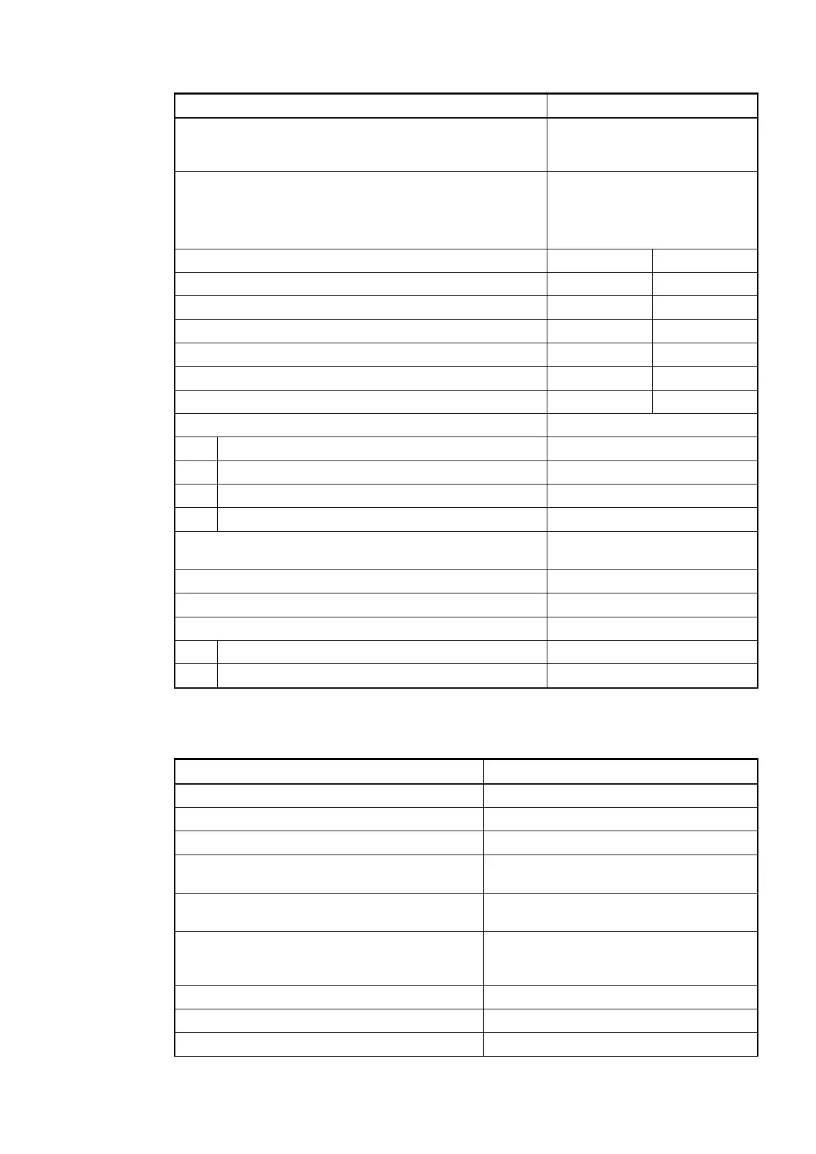
Parameter Value
Indication of the input signals 1 yellow LED per channel; the
LED is ON when the input signal
is high (signal 1)
Monitoring point of input indicator LED
It is not part of input circuit (its
controlled by processor side, not
process side)
Input type according to EN 61131-2 Type 1 source Type 1 sink
Input signal range -24 V DC +24 V DC
Signal 0 -5 V...+3 V -3 V...+5 V
Undefined signal -15 V...+ 5 V +5 V...+15 V
Signal 1 -30 V...-15 V +15 V...+30 V
Ripple with signal 0 -5 V...+3 V -3 V...+5 V
Ripple with signal 1 -30 V...-15 V +15 V...+30 V
Input current per channel
Input voltage +24 V Typ. 5 mA
Input voltage +5 V Typ. 1 mA
Input voltage +15 V < 3 mA
Input voltage +30 V < 7 mA
Max. permissible leakage current (at 2-wire proximity
switches)
1 mA
Input delay (0->1 or 1->0) Typ. 8 ms
Input data length 1 byte
Max. cable length
Shielded 500 m
Unshielded 300 m
6.2.3.8.2 Technical data of the digital outputs
Parameter Value
Number of channels per module 2 transistor outputs (24 V DC, 0.5 A max.)
Distribution of the channels into groups 1 group of 2 channels
Connection of the channels O0 to O1 Terminals 4 to 5
Reference potential for the channels O0 to O17 Terminal 7 (negative pole of the process
voltage, name ZP)
Common power supply voltage Terminal 6 (positive pole of the process
voltage, name UP)
Indication of the output signals 1 yellow LED per channel; the LED is on
when the output signal is high (signal 1)
and the module is powered via the I/O bus
Monitoring point of output indicator Controlled together with transistor
Way of operation Non-latching type
Min. output voltage at signal 1 UP - 0.1 V
Option boards > TA5110-2DI2DOT - Digital input/output module option board
2021/06/29 3ADR010635, 2, en_US 123
 Loading...


