4)
- With readback contact: Max reachable SIL acc. IEC 61508 (Typ A components are required) ➔ without
error exclusion (you can reach higher level up to SIL 3 with error exclusion)
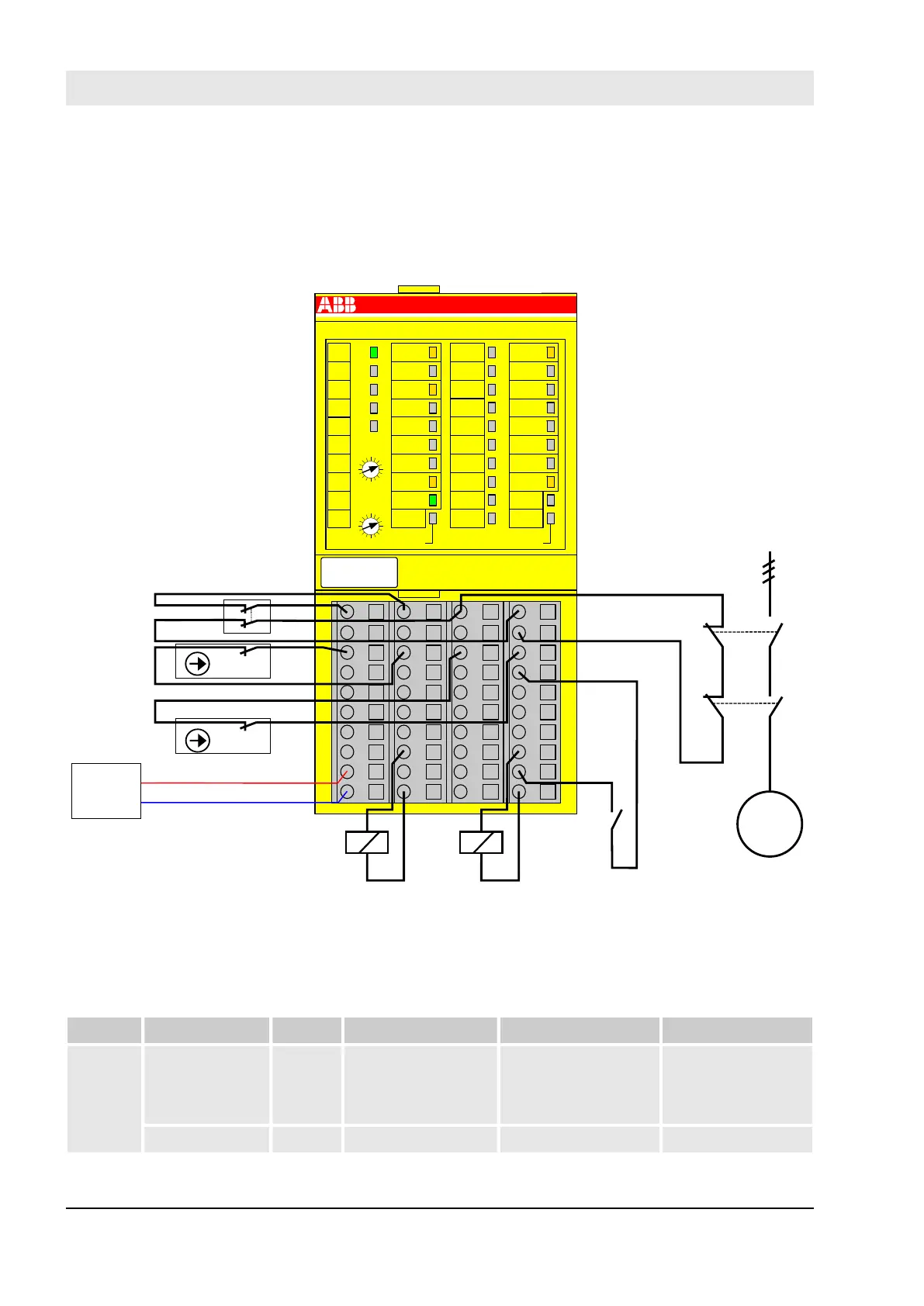
Application example
1.0
1.1
1.2
1.3
1.4
1.5
1.6
1.7
1.8
1.9
2.0
2.1
2.2
2.3
2.4
2.5
2.6
2.7
2.8
2.9
3.0
3.1
3.2
3.3
3.4
3.5
3.6
3.7
3.8
3.9
4.0
4.1
4.2
4.3
4.4
4.5
4.6
4.7
4.8
4.9
DX581-S
3.8
UP
3.9
ZP
3.7
3.0
T2
3.1
3.2
T3
3.3
3.5
3.4
3.6
UP 24VDC 100W
8SDI 8SDO
Safety Digital Input 24VDC
Safety Digital Output 24VDC 0.5A
ERR2
4.9
ZP
4.2I6
4.0
I4
4.1
I5
4.3
I7
4.4
O4
4.5
O5
4.6O6
4.7
O7
4.8
UP
ERR1
2.9
ZP
2.2I2
2.0
I0
2.1
I1
2.3
I3
2.4
O0
2.5
O1
2.6O2
2.7
O3
2.8
UP
PWR
1.9
ZP
1.8
UP
1.7
1.0
T0
1.2
T1
1.3
1.1
1.5
1.4
1.6
ADDR
x10H
ADDR
x01H
C
4
3
B
2
A
1
9
0
8
F
7
E
6
D
5
C
4
3
B
2
A
1
9
0
8
F
7
E
6
D
5
GND
24 VDC
User
acknowledgement
Feedback loop
3~
Motor
K2
K1
L
Safety door contact 2
Safety door contact 1
E-Stop
K1 K2
Fig. 48: Application example with DX581-S
3.4.8 LED status display
Table 8: Status display and its meaning
LED Description Colour LED = OFF LED = ON LED flashes
Inputs 0
… 7
Digital input Yellow Input = OFF Input = ON (the input
voltage is displayed
even if the supply
voltage is OFF).
--
Channel error Red No channel error Channel error --
AC500-S Safety Modules
DX581-S digital safety input/output module > LED status display
30.03.2017AC500-S126