3.5.8 LED status display
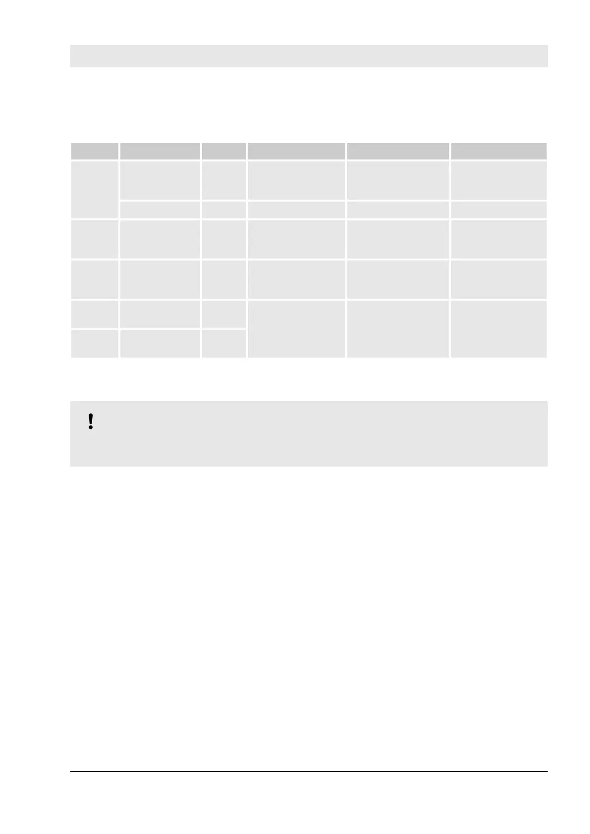
Table 9: Status display and its meaning
LED Description Colour LED = OFF LED = ON LED flashes
Inputs 0
… 3
Analog input Yellow Analog input = ca.
0 mA
Input = ON (LED light
intensity depends on
the input value)
--
Channel error Red No channel error Channel error --
UP Process voltage
+24 V DC via
terminal
Green Process supply
voltage is missing
Process supply
voltage OK
--
PWR +3.3 V voltage
from IO-Bus
Green +3.3 V IO-Bus
voltage is not avail-
able
+3.3 V IO-Bus
voltage is available
--
ERR1 Module error
indicator 1
Red No module error Module error which
leads to a SAFE
STOP state
Module passivation
and/or acknowl-
edgement request
(alternating blinking)
ERR2 Module error
indicator 2
Red
3.5.9 Technical data
NOTICE!
AI581-S-XC version is available for usage in extreme environmental conditions (
Ä
Appendix “System
data for AC500-S-XC” on page 446).
AC500-S Safety Modules
AI581-S analog safety input module > Technical data
30.03.2017 AC500-S 149