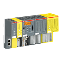
The following communication requirements shall be fulfilled for using AC500-S Safety PLC:
n Safety data cannot be transferred over public networks, e.g., Internet. If safety data is transferred across
company/factory networks, ensure that sufficient protection is provided against manipulation (firewall or
router for network separation).
n Equipment connected to communication devices shall feature safe electrical isolation.
NOTICE!
You can use AC500-S Safety I/O modules with 3
rd
party F-Hosts on PROFINET. Download and install
valid ABB GSDML files in your 3
rd
party F-Host engineering environment from http://www.abb.com/plc.
After this, you can configure and use AC500-S Safety I/Os with 3
rd
party F-Host. Use ABB PS501
Control Builder Plus V2.2.1 (or newer) / Automation Builder 1.0 (or newer) to obtain F_iPar_CRC value
for your configured iParameters or contact ABB technical support to obtain F_iPar_CRC values.
Validate that all iParameters (Input delay, channel configuration, etc.) for all AC500-S Safety I/Os and
other F-Devices are correct with a given F_iPar_CRC value using appropriate functional validation
tests or verification procedure (
Ä
Chapter 6.5 “Verification procedure for safe iParameter setting in
AC500-S Safety I/Os” on page 412) for those parameters.
2.13 Safety function and fault reaction
The main safety function of AC500-S Safety PLC is to read safety digital and analog inputs to control the
safety digital outputs by the safety logic module SM560-S according to a user-defined IEC 61131 application
program and configuration.
The AC500-S Safety PLC can be used as a “de-energize to trip” (Normally Energized, NE) system. The safe
state of the outputs is defined according to the table below:
Table 2: NE safety system behaviour
Normally energized, NE
Mode according to IEC 61508 ed. 2 High-demand
Safety Function De-energize to trip
Safe State De-energized outputs
The purpose of AC500-S safety function is to enable a machine (as a system) to achieve with a given SIL
(IEC 61508 ed. 2, IEC 62061) and PL (ISO 13849) a system safe state. An exemplary Safety Function on
the application level, which can be executed by AC500-S in machinery applications, is the Emergency Stop.
2.13.1 Safety CPU (SM560-S)
The safety function of SM560-S Safety CPU is to correctly process signal information. It processes safety
input signals and internal data storage to generate signals to safety output modules and set a new state of its
internal data storage.
If this function cannot be correctly executed, the SM560-S Safety CPU goes to a SAFE STOP state, in which
no valid safety telegrams are generated and, as a result, all safety output module channels are de-energized
(‘0’ state) after watchdog time is expired.
Faults in the cyclic communication between the Safety CPU and Safety I/O modules are detected by the
Safety CPU and, as a result, ‘0’ values are handed to the safety application program.
Overview of AC500-S Safety PLC
Safety function and fault reaction > Safety CPU (SM560-S)
30.03.2017AC500-S24

 Loading...