3.2.2 Safety I/O module states
Safety I/O module system states can be described using two state charts (Fig. 13 and Fig. 14). Fig. 13 pro-
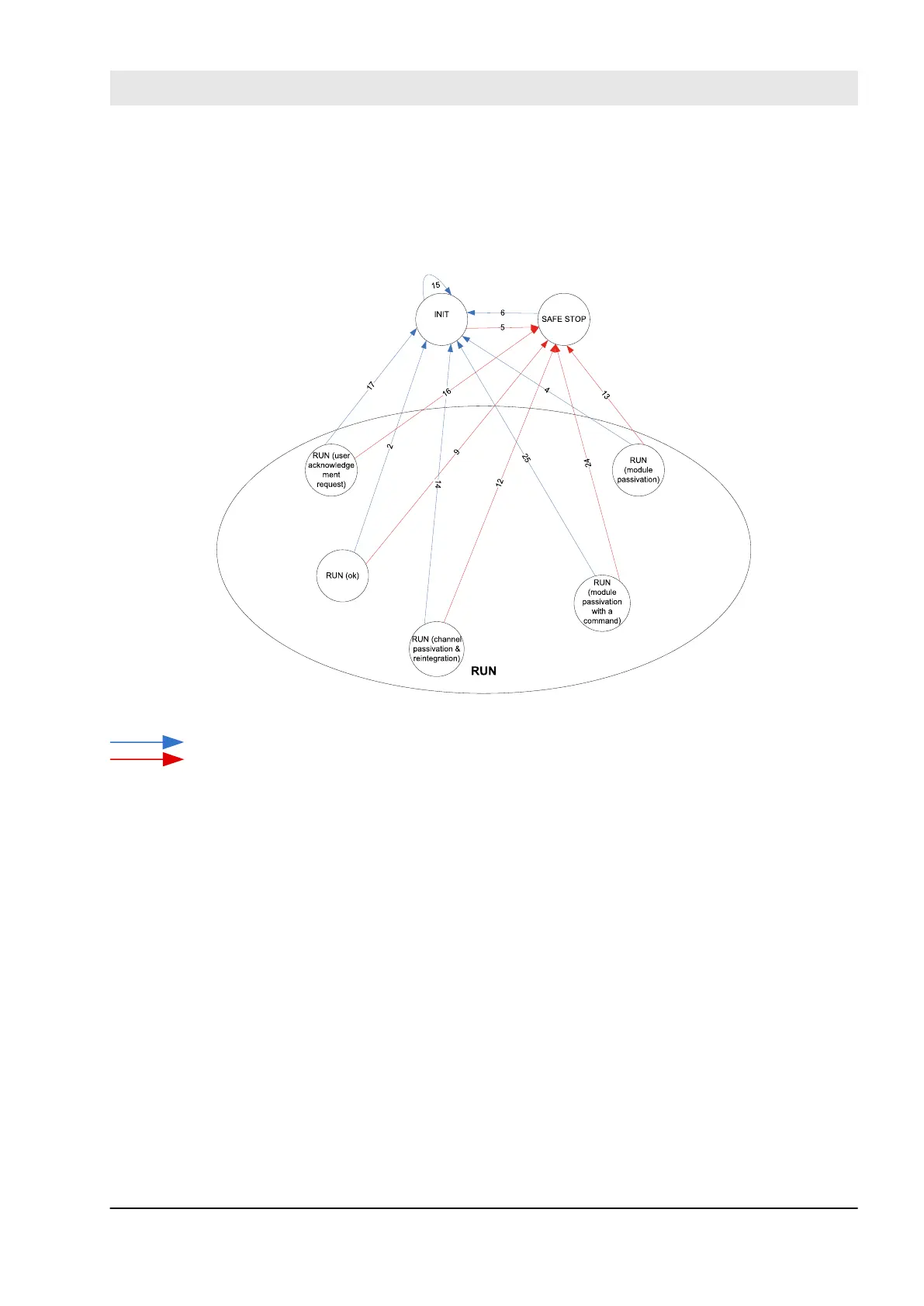
vides an overview of transitions related to powering off/on and fatal errors. Fig. 14 provides an overview on
the rest of transitions in Safety I/O modules.
Fig. 13: Overview of transitions related to powering off/on and fatal errors in Safety I/O modules
Powering off/on
Fatal error
AC500-S Safety Modules
Generic Safety I/O module behaviour > Safety I/O module states
30.03.2017 AC500-S 59