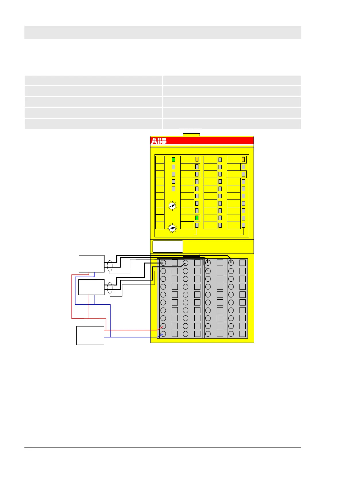
2 analog sensors (0 … 20 mA), external sensor power supply
2-channel evaluation In AI581-S module
Sensor power supply on channel 1 (I0) External 24 V DC (Sensor)
Sensor power supply on channel 2 (I2) External 24 V DC (Sensor)
SIL/Cat./PL
1), 2)
SIL 2/Cat.3/PL d
SIL
3)
SIL 3
1.0
1.1
1.2
1.3
1.4
1.5
1.6
1.7
1.8
1.9
2.0
2.1
2.2
2.3
2.4
2.5
2.6
2.7
2.8
2.9
3.0
3.1
3.2
3.3
3.4
3.5
3.6
3.7
3.8
3.9
4.0
4.1
4.2
4.3
4.4
4.5
4.6
4.7
4.8
4.9
AI581-S
UP 24VDC 2W
4SAI
Safety Analog Input
3.8
UP
3.9
ZP
3.4
3.7
3.0
I2-
3.1
FE
3.2
I3-
3.3
FE
3.5
3.6
ERR1
2.9
ZP
2.8
UP
2.3
2.4
2.5
2.1
2.7
2.6
2.2I1+
2.0
I0+
ERR2
4.8
UP
4.7
4.2I3+
4.0
I2+
4.6
4.5
4.4
4.3
4.1
PWR
1.9
ZP
1.8
UP
1.7
1.4
1.0
I0-
1.2
I1-
1.3
FE
1.1
FE
1.5
1.6
ADDR
x10H
ADDR
x01H
C
4
3
B
2
A
1
9
0
8
F
7
E
6
D
5
C
4
3
B
2
A
1
9
0
8
F
7
E
6
D
5
4.9
ZP
Sensor
0...20mA
24VDC
GND
Sensor
0...20mA
Fig. 56: Circuit example AI581-S, 2 analog sensors (0 … 20 mA)
1)
- MTTFd = High, DC = Medium
2)
- Max. reachable (ISO 13849, IEC 62061, EN 954) ➔ without error exclusion (you can reach higher levels
up to PL e, SIL 3, Cat. 4 with error exclusion)
3)
- Max. reachable SIL acc. IEC 61508 (Type A components are required) ➔ without error exclusion (you
can reach higher levels up to SIL 3 with error exclusion)
AC500-S Safety Modules
AI581-S analog safety input module > Circuit examples
30.03.2017AC500-S146
 Loading...


