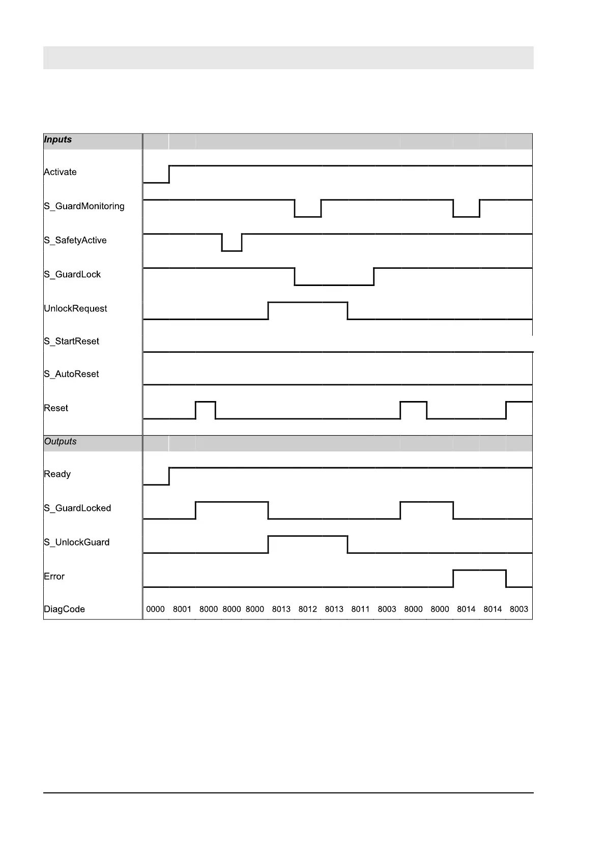
Typical Timing Diagram
Fig. 112: Timing diagram for SF_GuardLocking
Static signals are detected at Reset. Errors are detected at the Guard switches.
Error Behavior
In the event of an error the S_GuardLocked and S_UnlockGuard outputs are set to FALSE, the DiagCode
output indicates the relevant error code, and the Error output is set to TRUE.
An error must be acknowledged by a rising trigger at the Reset input.
Configuration and programming
AC500-S Libraries > SafetyBlocks_PLCopen_AC500_v22.lib
30.03.2017AC500-S320
 Loading...


