Name Data Type Initial Value Description, Parameter Values
Ready BOOL FALSE
Ä
Table 32 “General Output Parameters”
on page 267
S_AOPD_Out BOOL FALSE Safety related output, indicates status of the
muted guard.
FALSE: AOPD protection field interrupted and
muting not active.
TRUE: AOPD protection field not interrupted or
muting active.
S_MutingActive BOOL FALSE Indicates status of Muting process.
FALSE: Muting not active.
TRUE: Muting active.
Error BOOL FALSE
Ä
Table 32 “General Output Parameters”
on page 267
DiagCode WORD 16#0000
Ä
Table 32 “General Output Parameters”
on page 267
Notes: Line control of muting sensor signals must be active in the safety loop
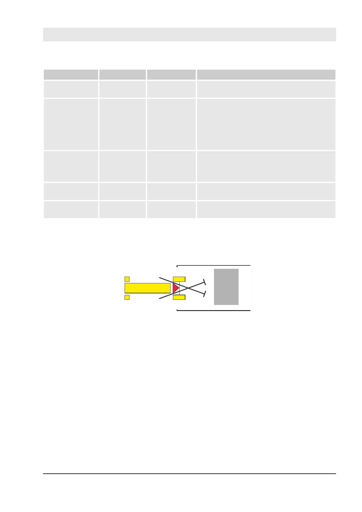
Example for SF_MutingPar_2Sensor with two reflecting light barriers
1
Transmitter
Receiver
Danger
zone
MS_11
MS_12
If reflection light barriers are used as muting sensors, they are generally arranged diagonally. In general, this
arrangement of reflection light barriers as muting sensors requires only two light barriers, and only
S_MutingSwitch11 (MS_11) and S_MutingSwitch12 (MS_12) are allocated.
Muting conditions
Muting condition 1 (to 8011) (MS_11 is the first entry switch actuated). Start timer DiscTimeEntry and Max-
MutingTime:
MutingEnable AND R_TRIG at MS_11 AND NOT MS_12
Muting condition 2 (to 8311) (MS_12 is the first entry switch actuated). Start timer DiscTimeEntry and Max-
MutingTime:
MutingEnable AND NOT MS_11 AND R_TRIG at MS_12
Muting condition 3 (from 8011 to 8012) (MS_12 is the second entry switch actuated):
Stop timer DiscTimeEntry:
MutingEnable AND MS_11 AND R_TRIG at MS_12
Configuration and programming
AC500-S Libraries > SafetyBlocks_PLCopen_AC500_v22.lib
30.03.2017 AC500-S 361


 To Next Page