Dimensions
1.0
1.1
1.2
1.3
1.4
1.5
1.6
1.7
1.8
1.9
2.0
2.1
2.2
2.3
2.4
2.5
2.6
2.7
2.8
2.9
3.0
3.1
3.2
3.3
3.4
3.5
3.6
3.7
3.8
3.9
4.0
4.1
4.2
4.3
4.4
4.5
4.6
4.7
4.8
4.9
1.0
1.1
1.2
1.3
1.4
1.5
1.6
1.7
1.8
1.9
2.0
2.1
2.2
2.3
2.4
2.5
2.6
2.7
2.8
2.9
3.0
3.1
3.2
3.3
3.4
3.5
3.6
3.7
3.8
3.9
4.0
4.1
4.2
4.3
4.4
4.5
4.6
4.7
4.8
4.9
DI581-S
UP 24VDC 5W
16SDI
Safety Digital Input 24VDC
3.8
UP
3.9
ZP
3.7
3.0
T4
3.1
3.2
T5
3.3
3.5
3.4T6
3.6T6
ERR2
4.9
ZP
4.2I10
4.0
I8
4.1
I9
4.3I11
4.4
I12
4.5I13
4.6I14
4.7
I15
4.8UP
ERR1
2.9
ZP
2.2I2
2.0
I0
2.1
I1
2.3I3
2.4
I4
2.5I5
2.6I6
2.7
I7
2.8UP
PWR
1.9
ZP
1.8
UP
1.7
1.0
T0
1.2T1
1.3
1.1
1.5
1.4T2
1.6T3
ADDR
x01H
4
C
3
B
2
A
1
9
0
8
F
7
E
6
D
5
ADDR
x10H
4
C
3
B
2
A
1
9
0 8
F
7
E
6
D
5
(2.27)
57.7
59 (2.32)
70.5 (2.78)
135 (5.31)
135 mm
(5.31) “
67.5 (2.66)
28
21 (0.83)
54 (2.13)
75 (2.95)
59 (2.32)
70.5 (2.78)
135 (5.31)
76 (2.99)
77 (3.03)
84.5 (3.33)
DIN rail 15 mm
DIN rail 7.5 mm
135 mm
(5.31) “
(1.10)
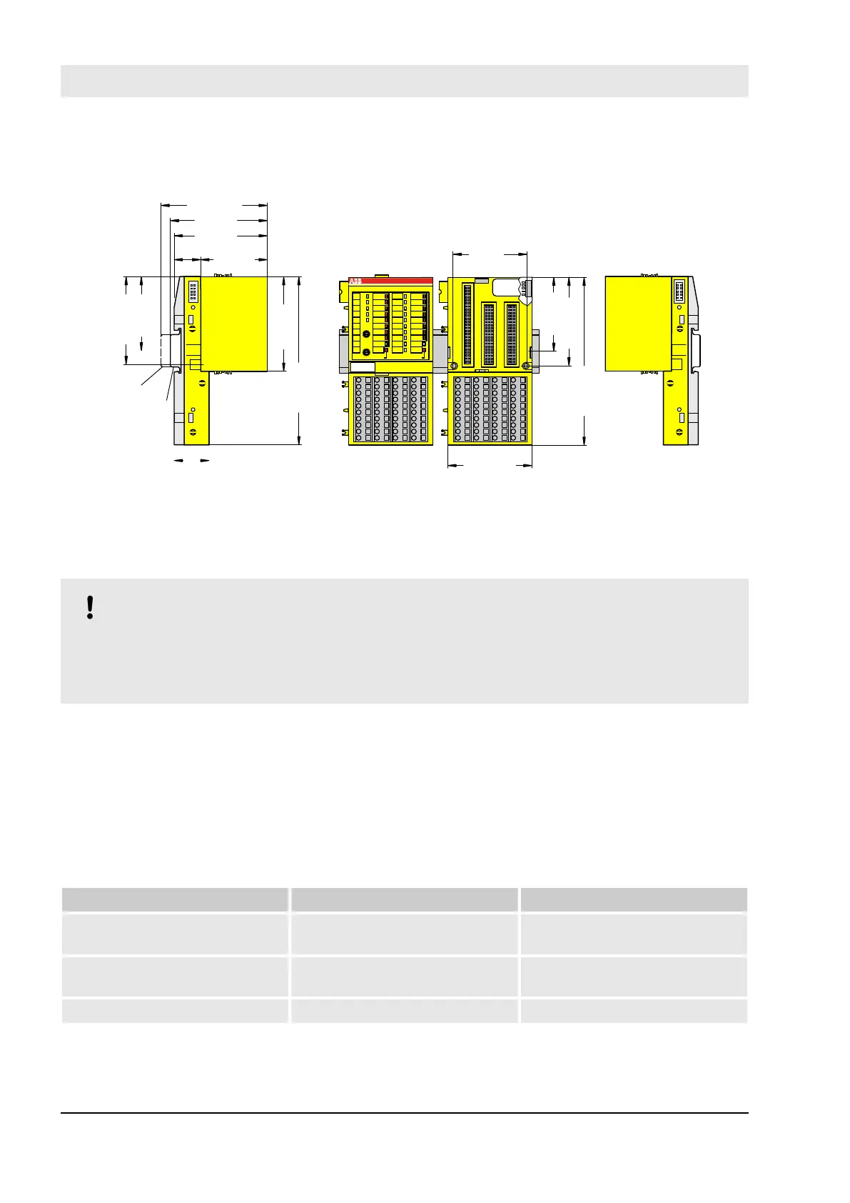
Fig. 21: Dimensions of DI581-S Safety I/O module
Electrical connection
NOTICE!
The same TU582-S is used by all AC500-S Safety I/O modules. If TU582-S is wired for DX581-S
module with Safety digital outputs and DI581-S or AI581-S modules are occasionally placed on this
Terminal Unit, under no circumstances it is possible that Safety digital output clamps on TU582-S
become energized due to a wrongly placed DI581-S or AI581-S Safety I/O modules.
The electrical connection of the I/O channels is carried out using 40 terminals of the I/O Terminal Unit. I/O
modules can be replaced without re-wiring the Terminal Units.
The terminals 1.8, 2.8, 3.8 and 4.8 as well as 1.9, 2.9, 3.9 and 4.9 are electrically interconnected within the
I/O Terminal Unit and have always the same assignment, independent of the inserted module:
n Terminals 1.8, 2.8, 3.8 and 4.8: Process voltage UP = +24 V DC
n Terminals 1.9, 2.9, 3.9 and 4.9: Process voltage ZP = 0 V
The assignment of the other terminals:
Terminals Signal Meaning
1.0, 1.2, 1.4, 1.6, 3.0, 3.2, 3.4, 3.6 T0, T1, T2, T3, T4, T5, T6, T7 Connectors of 8 test pulse outputs
T0, T1, T2, T3, T4, T5, T6, T7
2.0 … 2.7, 4.0 … 4.7 I0, I1, I2, I3, I4, I5, I6, I7, I8, I9,
I10, I11, I12, I13, I14, I15
16 safety digital inputs
1.8, 2.8, 3.8, 4.8 UP Process power supply +24 V DC
AC500-S Safety Modules
DI581-S digital safety input module > Mounting, dimensions and electrical connection
30.03.2017AC500-S82