____________________________________________________________________________________________________________
G1 Introduction to AC500 1-34 AC500 / Issued: 07.2006
You can use the following components to add additional I/O modules:
If you want … … use the following component(s):
• to connect a digital 24 VDC sensor or
actuator to the CPU …
DI524 (32 DI ), DC522 (16DC), DC523 (24DC),
DC532 (16DI/16DC) or DX522 (8DI/8 DO-R) with
the corresponding terminal unit with screw or
spring connection TU515/516 or TU531/532
• to connect a 115-230 VAC sensor or
actuator to the CPU ...
DX531 (8DI 115-230 V AC / 4 DO-R) +
corresponding Terminal Unit TU531/532 with
screw or spring technology
• to connect an analog 24 VDC sensor or
actuator to the CPU …
AI523 (16AI U/I/PT100), AO523 (16AO), AX521
(4AI/4AO U/I/PT100) or AX522 (8AI/8AO
U/I/PT100) + corresponding Terminal Unit
TU515/516
• to label the I/O channels …
TA523 (Pluggable Marking Holder) + TA525 Set
of Plastic Markers
The following components are recommended for fieldbus communication:
If you want … … use the following component(s):
• the system to act as a master on
PROFIBUS DP, DeviceNet or CANopen
fieldbuses …
CM572-DP for PROFIBUS DP, CM575-DN for
DeviceNet or CM578-CN for CANopen
• the system to act as a slave on
PROFIBUS DP, DeviceNet or CANopen
fieldbuses …
FieldBusPlug standard plugs like PDP22-FBP
(PROFIBUS DP slave) or DNP21-FBP
(DeviceNet) or other one’s
• to exchange data via the network …
CM577-ETH to achieve Ethernet TCP/IP
communication with integrated 2-ports switch
System planning
Consider the following when planning your AC500 system:
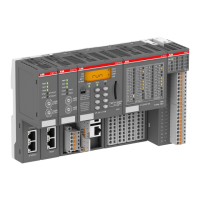
• The AC500 PLC consists of a CPU Terminal Base TB5xx (from 1 to 4 coupler slots) and a pluggable
CPU. Three different CPU classes are offered: from PM571 with 64kB memory up to PM591 with
4MB memory; available also with integrated Ethernet coupler.
• Proper CPU Terminal Base selection requires that sufficient slots are available for all current or
future network and fieldbus communication modules (e.g. Ethernet, ARCNET, PROFIBUS, etc.) if
required.
• Up to 4 communication couplers can be connected to the CPU through the dedicated CPU terminal
base.
• All types of external communication couplers can be used together in the same time but only up to 4
external couplers in total (e.g. a mix of coupler types like Ethernet + Ethernet + Profibus DP +
CANopen, etc …).
• The total number of communication couplers (internal + external) is limited to 5.
• The CPU terminal base is always the left-most device in the system.
• An external 24 Vdc power supply has to be provided to the CPU Cluster; the additional I/O modules
have to be installed to the right of the PLC module.
• The AC500 PLC module supports as many as 7 local I/O expansion modules.
• An additional process power supply has to be provided for the I/Os of each module. Each I/O
expansion module can be powered with its own power supply (for isolation purposes) or the same
power supply can also be used.
• One FieldBusPlug can be plugged directly into an AC500 PLC cluster

 Loading...


