____________________________________________________________________________________________________________
G1 Introduction to AC500 1-3 AC500 / Issued: 07.2006
Survey - gain an overview
System structure of AC500/S500-FBP
The principle system structure is shown in the following figure:
External
couplers
CPU
+
S500–FBP I/Os
(max. 7 modules)
DC505–FBP S500–FBP I/Os
(7 modules max.
with a maximum of
4 analog modules)
AC500
S500–FBP
(max. 4) internal
couplers
Explanation
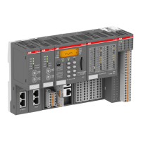
The following electronic modules are the basic components of the AC500 system:
• CPUs of three different performance classes
• Couplers for various bus systems: Fieldbus systems PROFIBUS DP, CANopen, DeviceNet; Ethernet
couplers.
Central expansion: One CPU supports direct connection of up to seven S500 FBP system I/O devices.
Decentralized expansion: Using the DC505 FBP interface module (for fieldbus systems PROFIBUS DP,
CANopen, DeviceNet, Modbus RTU), up to seven S500 FBP system I/O devices can be connected (with
a maximum of four analog modules).
Mechanical mounting of the electronic modules is done using CPU terminal bases (for the CPU and the
couplers) and I/O terminal units (for the I/O modules), designed for snap-on mounting on a DIN rail or for
screw-mounting on a mounting panel.

 Loading...


