____________________________________________________________________________________________________________
G1 Introduction to AC500 1-35 AC500 / Issued: 07.2006
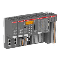
Steps for installation
√
Installation step: Further
information:
1 Snap the AC500 PLC Terminal Base onto DIN Rail or wall-mount with
screws.
2 Snap the additional Terminal Units for I/O modules onto DIN Rail
(optional) or screw them (wall mounting).
3 Make the sensor/actuator wire connections according to the dedicated
Electronic module you want to use. Provide external process power
supply as required.
(*)
4 If required, make the fieldbus connections according to the dedicated
master coupler module you want to use.
(*)
5 Plug the appropriate electronic and I/O modules in the correct locations
(CPU module, communication couplers on TB, and eventually also I/O
modules onto dedicated TUs).
6 Install the battery and the memory SD card; this is optional and the
CPU is able to run without them.
7 If required, make the FBP fieldbus slave connection according to the
chosen FBP and use the dedicated FBP accessories (cables, master
cable to M12, line termination, power supply connector, etc…).
(**)
8 If required, plug the FBP-Plug on the M12 connector located on the
CPU Terminal Base of the AC500 PLC.
9 Connect a programming cable (e.g. TK501 in COM2/PLC and
COM1/PC; TK502 is necessary for COM1/PLC) on the PC and on the
AC500 PLC.
10 Set the power on (process power supply first and PLC power supply).
11 If required, set the an address for the integrated Ethernet
communication interface by using the front face LCD Display +
keyboard of the CPU module (see the dedicated chapter of the user’s
manual).
12 Install the AC500 Control Builder programming software on your PC. If
required, also copy the appropriate EDS/GSD files into the Fieldbus
configurator (AC500 Control Builder) to manage the possible fieldbus
slave modules connected to the AC500 master couplers.
(*)
13 Program the hardware configuration.
(*) Refer to the AC500 hardware description for proper wiring and addressing information.
(**) Refer to the Installation Instructions for the particular FBP devices. Follow appropriate fieldbus
practices outline by the conventions and standards of each protocol used in the system.

 Loading...


