____________________________________________________________________________________________________________
G1 Introduction to AC500 1-45 AC500 / Issued: 07.2006
1
2
1
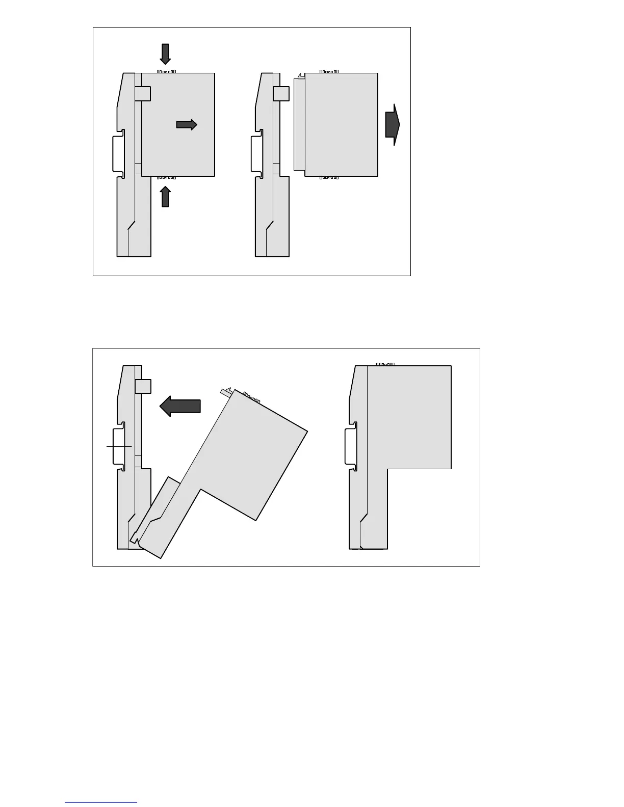
Figure: CPU / I/O Module disassembly
For disassembly, press top and bottom, then pull out the CPU / I/O module.
Step 5: Communication Couplers on Terminal Base assembly
Figure: Mounting of a communication coupler (CM5xx) on a CPU Terminal Base (TB5xx)
First insert the bottom nose of the communication Coupler module into the dedicated holes of the
Terminal Base and then rotate the coupler until it will be plugged on the dedicated Terminal Base slot,
push to be sure that the connection is well done. It will be locked in place.
The disassembly is done in reverse order.

 Loading...


