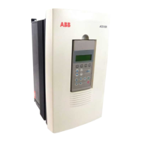
Appendix A – ACS/ACC/ACP 601 Technical Data
ACS/ACC/ACP 601 Drives ACx=ACS/ACC/ACP A-7
External Control
Connections (NIOC)
External control connections of ACS 600 with standard application
software (Factory Macro) are below. External control connections are
different with other application macros and softwares (see
Firmware
Manual
).
ACS 601/604/607
NIOC Board
(A2)
Programmable I/O
Factory Settings
X21
1 VREF Reference voltage 10 V d.c.
1 kΩ <
R
L
< 10 kΩ
2GND
3 AI1+ Speed reference
0(2) ... 10 V
R
in
> 200 kΩ
4AI1-
5 AI2+ By default, not in use.
0(4)... 20 mA
, R
in
= 100 Ω
6AI2-
7 AI3+ By default, not in use.
0(4)... 20 mA
, R
in
= 100 Ω
8AI3-
9 AO1+ Motor speed 0(4)...20 mA
0...motor nom. speed,
R
L
< 700 Ω
10 AO1-
11 AO2+ Output current
0(4)...20 mA
0...motor nom. current,
R
L
< 700 Ω
12 AO2-
X22
1 DI1 Start
2 DI2 Stop
3 DI3 Forward / Reverse
1)
4 DI4 ACCEL/DECEL 1/2
5 DI5 Constant speed select
2)
6 - Constant speed select
2)
7 +24V +24 V d.c. max. 100 mA
8 +24V
9 DGND Digital Ground
X23
1 +24 V Auxiliary voltage output, non-
isolated, 24 V d.c. 250 mA
2GND
X25
1 RO11 Relay output 1
Ready
2RO12
3RO13
X26
1 RO21 Relay output 2
Running
2RO22
3RO23
X27
1 - Relay output 3
Fault (-1)
2-
3-
=
=
2)
Operation: 0 = Open, 1 = Closed
DI 5 DI 6 Output
0
1
0
1
0
0
1
1
Set speed through AI1
Constant Speed 1
Constant Speed 2
Constant Speed 3
1
2
3
5
6
TRANS
Power to link
Link Connections
B-
A+
GND
+24 V
Connector X29 for RS 485 connection
4
FAULT
1
2
3
4
5
6
TRANS
Power to link
Link Connections
GND
B-
A+
GND
+24 V
Connector X28 for RS 485 connection
1)
Parameter 10.3 must be set to REQUEST.
Terminal Block Size
X21, X22, X23, X25, X26, X27: cables 0.5 to 1.5 mm
2
(#20 to #16 AWG)
X2: cables 0.5 to 2.5 mm
2
(#20 to #14 AWG)
Control Cable Lead-through Size:
Ø: 2 x 3x2...11 mm (IEC units)
Factory settings of application software
selection B (type code):
DI1: Start, DI2: Stop, DI3: Reverse, DI4:
Acc/Dec 2, DI5,6: Constant speed 1 to 3 select.
Fault
A
rpm

 Loading...