Appendix B – ACS/ACC/ACP 601 Dimensional Drawings
ACS/ACC/ACP 601 Drives ACx=ACS/ACC/ACP B-11
ACP 601 Control
Cable Connections
The deliveries include a bag with four clamps, screws and copper tape
(frame size R4 also an assembly plate). Clamp the control and encoder
cables as explained below. If more than four cables are needed,
connect the twisted screen (grounding wires) of the additional cables
as short as possible to the grounding rail next to the NIOC(P)
board. Clamping is very important with the encoder cable but less so
with relay and other digital signal cables.
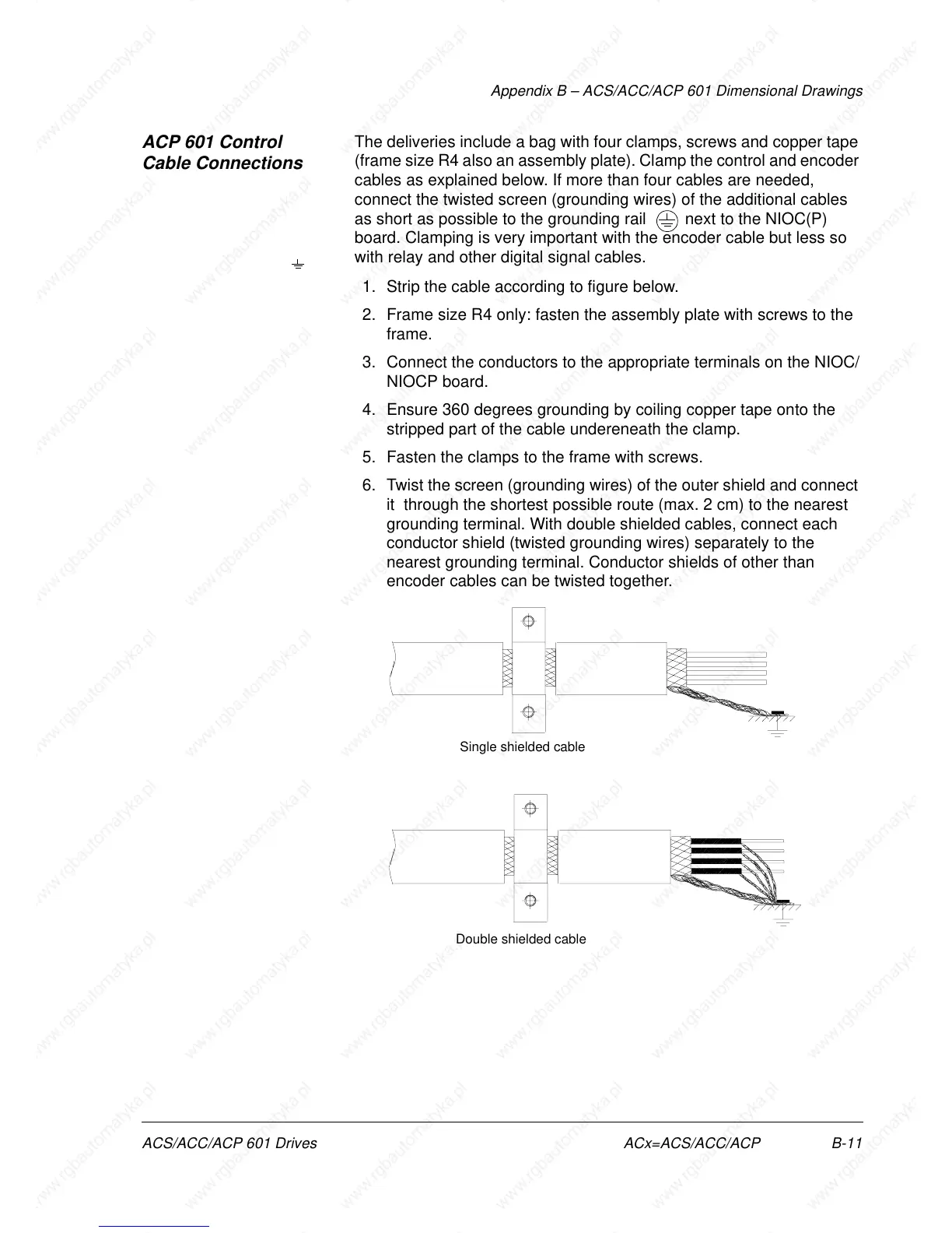
1. Strip the cable according to figure below.
2. Frame size R4 only: fasten the assembly plate with screws to the
frame.
3. Connect the conductors to the appropriate terminals on the NIOC/
NIOCP board.
4. Ensure 360 degrees grounding by coiling copper tape onto the
stripped part of the cable undereneath the clamp.
5. Fasten the clamps to the frame with screws.
6. Twist the screen (grounding wires) of the outer shield and connect
it through the shortest possible route (max. 2 cm) to the nearest
grounding terminal. With double shielded cables, connect each
conductor shield (twisted grounding wires) separately to the
nearest grounding terminal. Conductor shields of other than
encoder cables can be twisted together.
Single shielded cable
Double shielded cable