Appendix A – ACS/ACC/ACP 601 Technical Data
A-8 ACx=ACS/ACC/ACP ACS/ACC/ACP 601 Drives
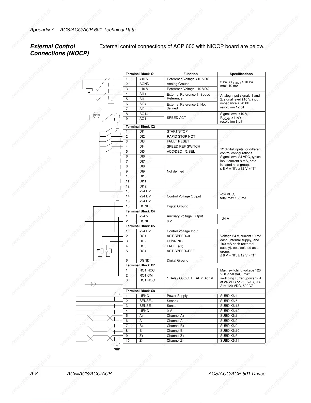
External Control
Connections (NIOCP)
External control connections of ACP 600 with NIOCP board are below.
Terminal Block X1 Function Specifications
1 +10 V Reference Voltage +10 VDC
2 kΩ ≤ R
LOAD
≤ 10 kΩ
max. 10 mA
2 AGND Analog Ground
3 –10 V Reference Voltage –10 VDC
4AI1+
External Reference 1: Speed
Reference
Analog input signals 1 and
2, signal level ±10 V, input
impedance ≥ 20 kΩ,
resolution 12 bit
5AI1–
6AI2+
External Reference 2: Not
defined
7AI2–
8AO1+
SPEED ACT 1
Signal level ±10 V,
R
LOAD
≥ 1 kΩ ,
resolution 8 bit
9AO1–
Terminal Block X2
1 DI1 START/STOP
12 digital inputs for different
control configurations.
Signal level 24 VDC, typical
input current 8 mA, opto-
isolated as a group,
≤ 8 V = “0”; ≥ 12 V = “1”
2 DI2 RAPID STOP NOT
3 DI3 FAULT RESET
4 DI4 SPEED REF SWITCH
5 DI5 ACC/DEC 1/2 SEL
6DI6
Not defined
7DI7
8DI8
9DI9
10 DI10
11 DI11
12 DI12
13 +24 DV
Control Voltage Output
+24 VDC,
total max 135 mA
14 +24 DV
15 +24 DV
16 DGND Digital Ground
Terminal Block X4
1 +24 V Auxiliary Voltage Output
+24 V
2DGND 0 V
Terminal Block X5
1 +24 DV Control Voltage Input
2 DO1 ACT SPEED=0 Voltage 24 V, current 10 mA
each (internal supply) and
100 mA each (external
supply), optoisolated as a
group,
≤ 8 V = “0”; ≥ 12 V = “1”
3 DO2 RUNNING
4DO3 FAULT (-1)
5 DO4 ACT SPEED=REF
6 DGND Digital Ground
Terminal Block X7
1 RO1 NCC
1 Relay Output, READY Signal
Max. switching voltage 120
VDC/250 VAC, max
switching current/power 2 A
at 24 VDC or 250 VAC, 0.4
A at 120 VDC, 500 VA
2RO1 CM
3RO1 NOC
Terminal Block X8
1 UENC+ Power Supply SUBD X6:4
2 SENSE+ Sense+ SUBD X6:5
3 SENSE– Sense– SUBD X6:13
4 UENC– 0 V SUBD X6:12
5 A+ Channel A+ SUBD X6:1
6 A– Channel A– SUBD X6:9
7 B+ Channel B+ SUBD X6:2
8 B– Channel B– SUBD X6:10
9 Z+ Channel Z+ SUBD X6:3
10 Z– Channel Z– SUBD X6:11
rpm