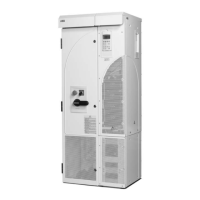
The ACS800-02/U2
25
Operation
This table describes the operation of the main circuit in short.
Printed circuit boards
The drive contains the following printed circuit boards as standard:
• main circuit board (AINT)
• motor control and I/O board (RMIO-02) with a fibre optic link to the AINT board
• input bridge control board (AINP)
• input bridge protection board (AIBP) which includes varistors, snubbers for the
thyristors
• power supply board (APOW)
• gate driver control board (AGDR)
• diagnostics and panel interface board (ADPI)
• EMC filter boards (NRFC) with option +E202
• brake chopper control board (ABRC) with option +D150
Motor control
The motor control is based on the Direct Torque Control (DTC) method. Two phase
currents and DC link voltage are measured and used for the control. The third phase
current is measured for earth fault protection.
Component Description
six-pulse rectifier converts the three-phase AC voltage to DC voltage
capacitor bank energy storage which stabilizes the intermediate circuit DC voltage
six-pulse IGBT inverter converts the DC voltage to AC voltage and vice versa. The motor
operation is controlled by switching the IGBTs.

 Loading...