Installation
49
Installation procedure
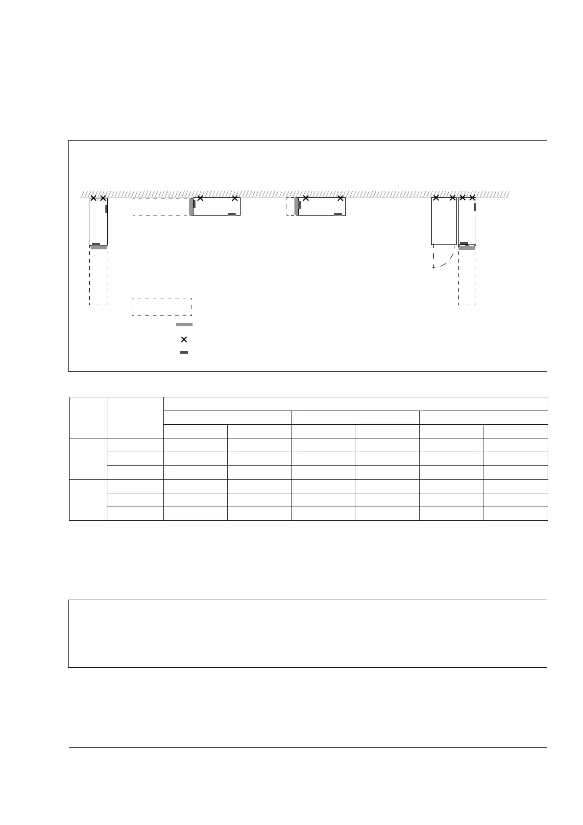
Choose the mounting orientation (a, b, c or d)
* space for the installer not included
** space for fan and capacitor replacement not included
Mounting orientations a and b
Frame
size
Mounting
orientation
Required free space around the unit for mounting, maintenance, service and cooling *
Front Side Above
mm in. mm in. mm in.
R7 a, d 500 20 - - 200 7.9
b - - 500 20 200 7.9
c - - 200** 7.9** lifting space lifting space
R8 a, d 600 24 - - 300 12
b - - 600 24 300 12
c - - 300** 12** lifting space lifting space
Make holes in the wall (recommended):
1. Lift the unit against the wall into the mounting place.
2. Mark the locations for the two fixing points in the wall (not for mounting orientation a if the unit is
subjected to sideways vibration).
3. Mark the bottom edges of the unit to the floor.
With enclosure extensionLifted from above
a) b) c)
air inlet surface
d)
wall fixing point (recommended)
control panel mounting slot
required free space
Note: The unit can also be installed away
from the wall.
Symbols:

 Loading...


