Connecting the CoreSense M10 61
Establishing optical Ethernet connections
connector. Before connecting the optical transceiver, see “Communication” on page 86 for more
information on the optical characteristics. Make sure optical power levels and wavelength are within the
specified range.
NOTICE
Do not use the copper-based SCADA Ethernet port when using the optical Ethernet port.
For more information on the various communication cables used, see Table 4 on
page 24 and “Connector definitions” on page 89.
For more information on configuring the communication protocols, refer to the
CoreSense M10 Monitoring System User Guide.
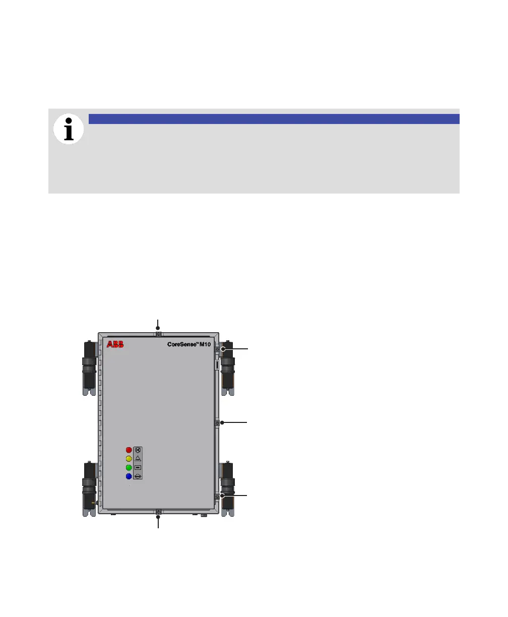
Closing the analytical unit door
To ensure that the unit remains compliant when you close the unit door, you must tighten the unit latch
screws to 9 N·m (80 lbf.in) according to the sequence indicated below:
—
Figure 46 CoreSense M10 door latch tightening sequence
1
2
3
4
5
6
7
8
9
j
 Loading...