Modbus-RTU Example Connection A-9MN448
Register 163: Display Scaling
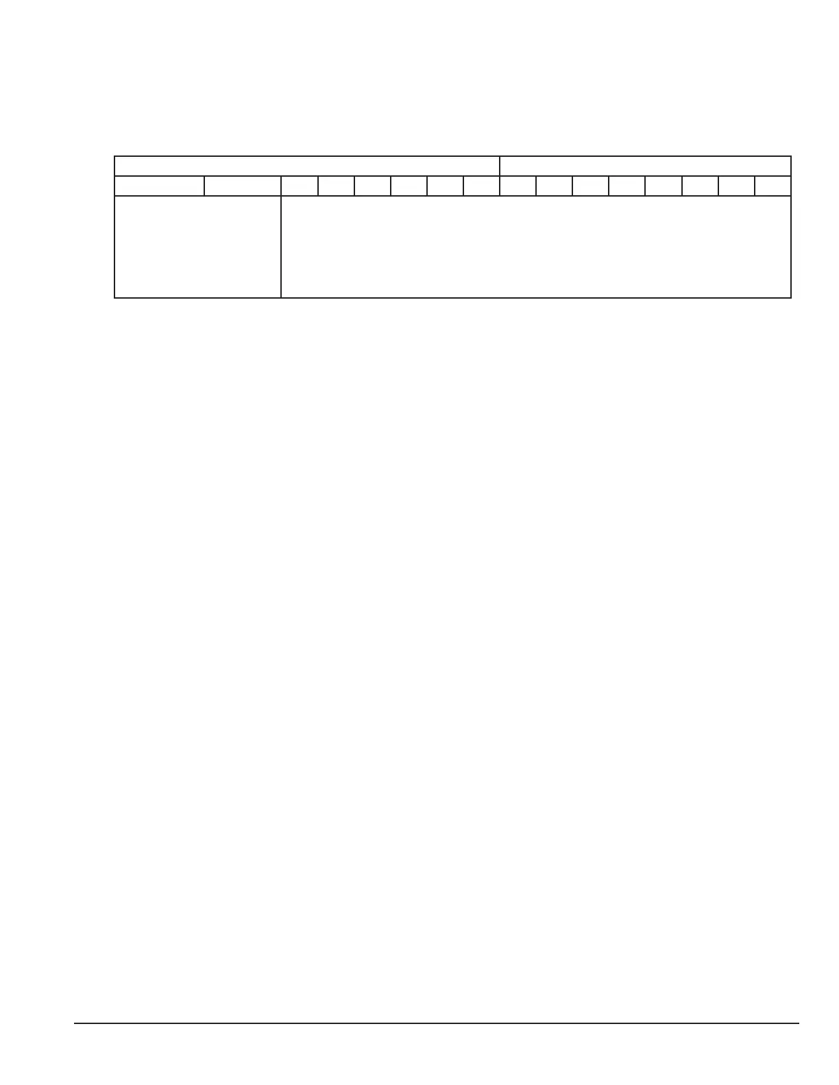
The parameter value is stored as a combined 16 bit word which is constructed as follows:
High byte Low byte
15 14 13 12 11 10 9 8 7 6 5 4 3 2 1 0
Display Scaling Source Display Scaling Factor : 3dp, e.g. 0 – 16000 = 0.000 – 16.000
0 : Motor Speed
1 : Motor Current
2 : Analog Input 2 Signal
3 : PI Feedback
A.10 Modbus Exception Response Telegrams
Under some circumstances, the drive may reply with an Exception Response (error) in response to a request telegram sent
from the network master, for example where the master tries to read a register which does not exist. Exception Responses
which can be generated by the drive are listed below:
Exception Code 1: Invalid Request
Exception Code 2: Invalid Modbus register
Exception Code 3: Register Value Out of Range
Exception Code 6: Drive Busy
Exception codes may be returned under the following conditions:
• Network Master sends an unsupported Modbus command (e.g. Read Coils).
• Run command issued to drive whilst the drive is not set for Modbus Control Mode (e.g. 1103 <>4).
• Run command issued to drives whilst the drive is not enabled (e.g. Digital Input 1 is open).
• Run command issued to drive whilst the drive is in a tripped condition.
• Network Master attempts to read or write a register that does not exist within the drive.
• Network Master attempts to write a holding register with a value outside the range of the register
• Drive busy due to internal data transfer. The Network Master should re-send the message after a delay
A.11 Dataflow Example
Read data from register 6
Request: [01] [03] [00] [05] [00] [01] [94] [0B]
(Drive Addr) (Command) (Reg start addr) (No. of Registers) (Checksum)
Reply: [01] [03] [02] [00] [00] [B8] [44]
(Drive Addr) (Command) (No of data bytes) (Data) (Checksum)
Note: The actual start address of register 6 is 5. All data in [ ] is in 8bits Hex format.
Write start command to the register 1 (suppose 1103 = 3, 9902 =0 and digital input 1 is closed):
Request: [01] [06] [00] [00] [00] [01] [48] [0A]
(Drive Addr) (Command) (Reg addr) (Data value) (Checksum)
Reply: [01] [06] [00] [00] [00] [01] [48] [0A]
(Drive Addr) (Command) (Reg addr) (Data value) (Checksum)
Note: The actual address of register 1 on the data link is 0. All data in [ ] is in 8bits Hex format.
Reply can be error message depending on drive parameter settings and digital input status.