S P I R I T
IT
F L O W- X INS T R U C T I O N M A N U A L | I M/ F L O W X - EN 7
3 The Spirit
IT
Flow-X products
Introduction
This chapter provides an overview of available models in the
Spirit
IT
Flow-X product suite.
Flow modules
All products are based on the same flow module (Flow-X/M). A
module usually represents one stream in your metering system.
The module has its own 4-line display and 4 navigation buttons
to allow inspection of values and changing of parameters if
required.
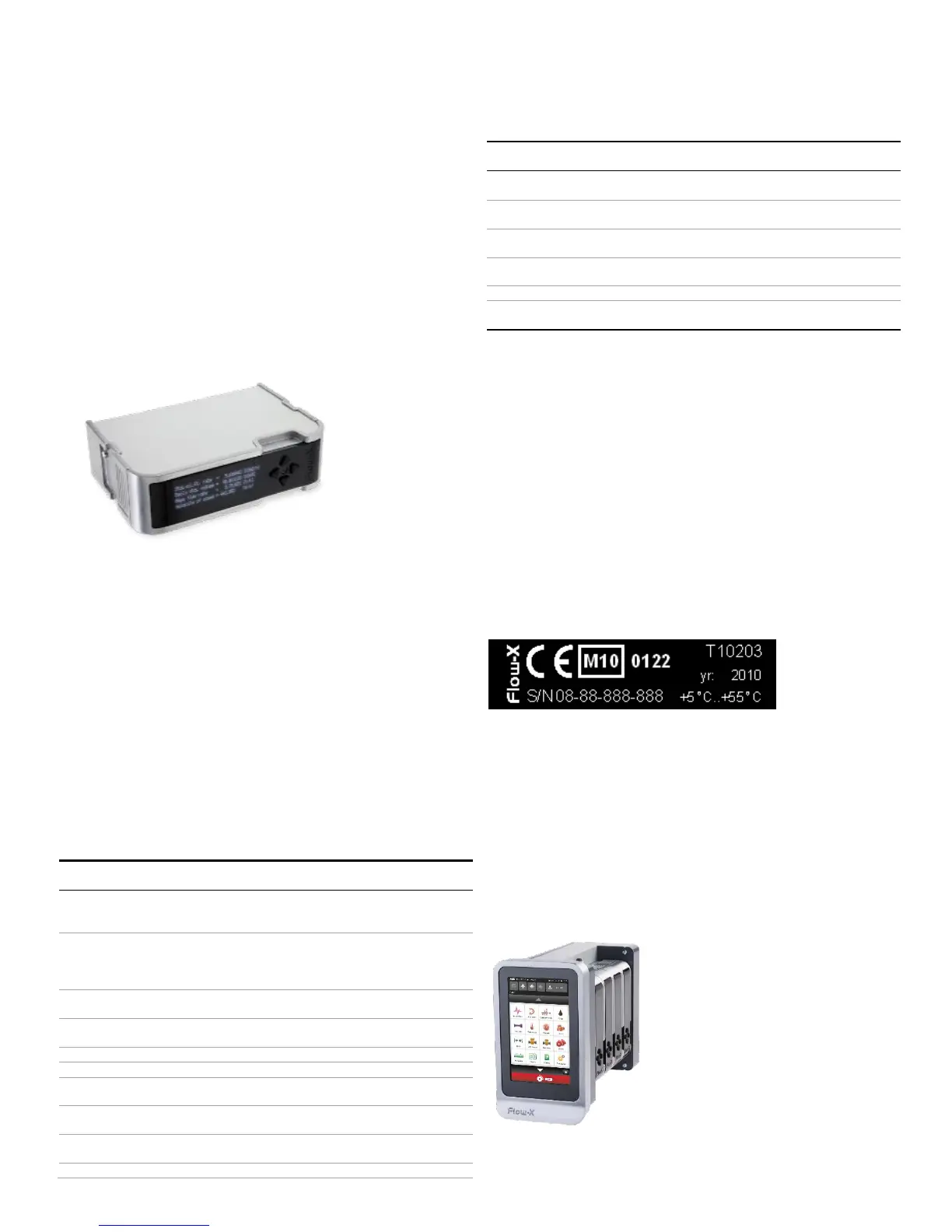
Figure 3-1 Flow-X/M Module
Flow modules are to be mounted in one of the following
enclosures:
A Panel mounted flow computer (maximum 4 modules),
Flow-X/P
A Panel mounted internal single module flow computer,
Flow-X/C
A Rack frame, holding maximum 8 modules, Flow-X/R
A single enclosure, Flow-X/S
A single rack enclosure, Flow-X/K
These enclosures are described in more detail below.
A single module has the following I/O capabilities:
Analog transmitter input, high accuracy
4-20mA, 0-20mA, 0-5V, 1-5V
Inputs are fully floating (optically isolated)
Independent HART loop inputs, on top of the 4-20mA
signals (Analog inputs)
Support includes multi-drop for each transmitter
loop
High accuracy PT-100 inputs
High speed single or dual pulse input. Frequency
range 0-5kHz (dual pulse) or 0-10kHz (single pulse)
Periodic time input, 100μs - 5000μs.
Digital output, open collector
Open collector, max. 100 Hz
Open collector, max. 10 kHz (Only available for Flow-
X/C device type)
Supports 1, 2 and 4 detector configurations mode
Analog output for flow control, pressure control
4-20mA, outputs floating.
Pulse output for proving applications
The output represents the corrected pulse signal
RS485/RS232 serial input for ultrasonic meter,
printer or generic, 115kb
RJ45 Ethernet interface, TCP/IP
External, 20 - 32 VDC, nominal 24 VDC, with
redundant connections
1 The maximum number of Analog inputs plus Hart inputs is 6
2 There are in total 16 in- and outputs available for these functions
3 Flow X hardware version 1 or version 2.
Table 3-1 Summary of Flow-X/M inputs and outputs
A full description of all specifications, including accuracies and
acceptable signal levels, is to be found in Chapter 7 – Technical
Specifications.
Nameplate
The Flow-X/M nameplate contains the following information: CE
marking, MID approval number, notified body, serial number,
year of build, operating temperature according to MID approval
(actual operating temperature is 0 to 60 °C) and test certificate
number.
Figure 3-2 Flow-X/M nameplate
Enclosures
Flow-X/P
This is a Panel mounted flow computer with up to four streams
and an additional station module with a 7” multi-lingual color
touch-screen and additional serial (3x) and Ethernet interfaces
(2x). This flow computer can be used in both horizontal and
vertical position. Field connections are available in standard 37-
pin and 9-pin D-Sub type connectors at the rear.
Figure 3-3 Flow-X/P Panel version