S P I R I T
IT
F L O W- X INS T R U C T I O N M A N U A L | I M/ F L O W X - EN 21
Ethernet
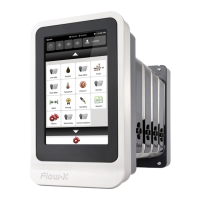
The Flow-X/K, Flow-X/C, Flow-X/S and Flow-X/P flow computers
provide two standard RJ-45 Ethernet connections.
The Flow-X/R rack provides 16 Ethernet connections, 2 for each
flow module in the corresponding slot. Whether or not these
Ethernet plugs can be used for communication depends on the
software configuration. When the corresponding flow module
operates autonomously, so not in a multi-module configuration,
the two Ethernet connections can be used to communicate with
the flow module. This is also true when the flow module is the
'first' flow computer in a multi-module configuration. 'First'
means first in the software application, which does not
necessarily correspond with the physical position within the
rack.
Break-out board connection details
Power supply
The power supply of the Flow-X/B can be either from an external
24V DC power supply or a Flow-X/M module.
There are two separate connectors for both, both with a
separate fuse and a red indicator LED (which will light up when
the fuse is blown). The external power supply connection is
protected by a 1.6 A (fast) fuse and the Flow-X/M power
connection by a 500 mA (fast) fuse.
By setting a jumper you can select the power source for the
board. A green indicator LED will light in case the selected power
supply is not blown.
The available separated flow computer grounds are all available
on one connector. These grounds are:
DIG_GND: Digital ground (two screw terminals)
AO_GND: Analog output ground
AI_GND: Analog input ground
Serial communication
Each Flow-X/B has one serial communication connection.
The serial connection terminals are combined in one 5-pin
connector. The signals on the connector pins depend on the
communication protocol:
* RS-232 | RS-485 2 wire | RS-485 4 wire
The Flow-X/B does not contain protection serial communication
signals.
PRT inputs
A Flow-X/B has one PRT connection. The signals are combined in
one 4 pin connector. The available PRT connector pins are:
The Flow-X/B does not contain protection of the PRT input
signals.
Analog inputs
Three analog input connections are available on a Flow-X/B.
Every Analog input connection has a separate 3 pin connector:
AI_Sig_N (where N is the Analog output number)
AI_24_V_Out_N (where N is the Analog output number)
All AI_24_V_Out_N (where N is the analog input number) are fuse
(1.6 A) protected.
A red indicator led will light in case the AI_N fuse is blown.
The (leaking) current through the led does not influence the
Analog Input value (is flow computer measurement).
All AI_24_V_Out_N (where N is the analog input number) provide
power from the same source selected using the jumper
described in section Power supply
Each Analog input has a high precision resistor of 250 Ω between
the AI_SIG and AI_GND that can be enabled/disabled using a
jumper. The precision of the resistor is that high that the
accuracy of the Analog Input is equal to the Flow computer
Analog input accuracy.
Analog outputs
Two analog output connections are available on a Flow-X/B.
Every analog output has a separate three pin connector:
AO_Sig_N (Where N is the Analog output number)
Analog output signals (AO_Sig_N) are not protected. They are
directly connected to the Analog outputs of the D-Sub 37
connector from the flow computer.
The 24_V_Out pin of the Analog output connectors provides
power from the same source as other 24_V_Out pins available in
other connectors.
Digital inputs / outputs Flow-X/B
A Flow-X/B has 8 Digital IO connections. Each digital IO
connection has a 5 pin connector:
DIG_SIG_N (Where N is the Digital IO port number)
EXT_SIG_N (Where N is the Digital IO port number)
EXT_RET_N (Where N is the Digital IO port number)
 Loading...

