S P I R I T
IT
F L O W- X INS T R U C T I O N M A N U A L | I M/ F L O W X - EN 19
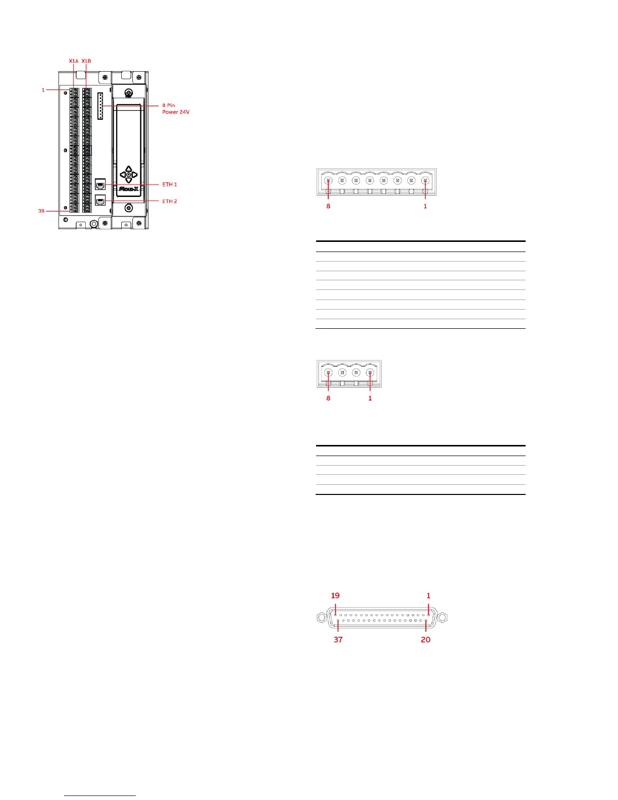
Figure 6-1 Flow-X/S connectors and terminals
Flow-X/K
The Flow-X/K has room for 1 module. The module is connected
through two D-sub 37 connectors (Port A and Port B). For the
pin-out see page 19.
In addition, the Flow-X/K enclosure has a 24V power connector
and 2 Ethernet connectors (LAN A and LAN B). For the power
connector see page 19.
Flow-X/B
The Flow-X/B board connects through a D-sub 37 connector to a
Flow-X/R, Flow-X/K, Flow-X/P or Flow-X/C enclosure. A fully
wired Flow-X/M module or Flow-X/C requires two Flow-X/B
boards. The D sub 37 connector is electrically connected to the
earth connection of the Flow-X/B. For the pin-out see chapter D-
sub 37 connectors on page 19.
Flow-X/B contains different types of inputs and outputs to
connect field signals. The protection depends on the type of
input/output.
All field signal connectors on the Flow-X/B have connectors with
screw terminals in the contra part of the connector.
All signals related to one input or output are combined in one
connector.
Each connector has per pin a short descriptive name at the
side the wires leaving the connector.
Each connector has the input/output name at the other side
of the connector. This name is also affixed on the contra part
of the connector
All inputs/outputs have the type and number of the A
connector affixed next to the connector. The input/output
number of the B Connector is between parentheses.
For more elaborate information on the connectors of the Flow-
X/B, see chapter Break-out board connection details on page 21.
Enclosure connector details
Power supply
The Spirit
IT
Flow-X flow computer provides redundant power
connections that may be connected to two power supplies. The
two power supplies may operate independently and there is no
need for a redundant power supply. When the in-use power
supply fails, the flow computer will automatically switch to the
other power supply without any loss of power.
The Flow-X/P and /S flow computers use an 8-pin terminal block
for connecting one or two external 24 Vdc power supplies, while
the Flow-X/R, /C and /K use a 4-pin terminal block. The primary
connection must always be used, the secondary is optional.
The primary power supply must be connected to a (the) '24 Vdc -
Primary' terminal and one of the '0 - Vdc' terminals. The optional
secondary power supply must be connected to a (the) '24 Vdc -
Secondary' terminals and one of the '0 V' terminals.
Figure 6-2: Flow-X/P version 1 & Flow-X/S power terminal block