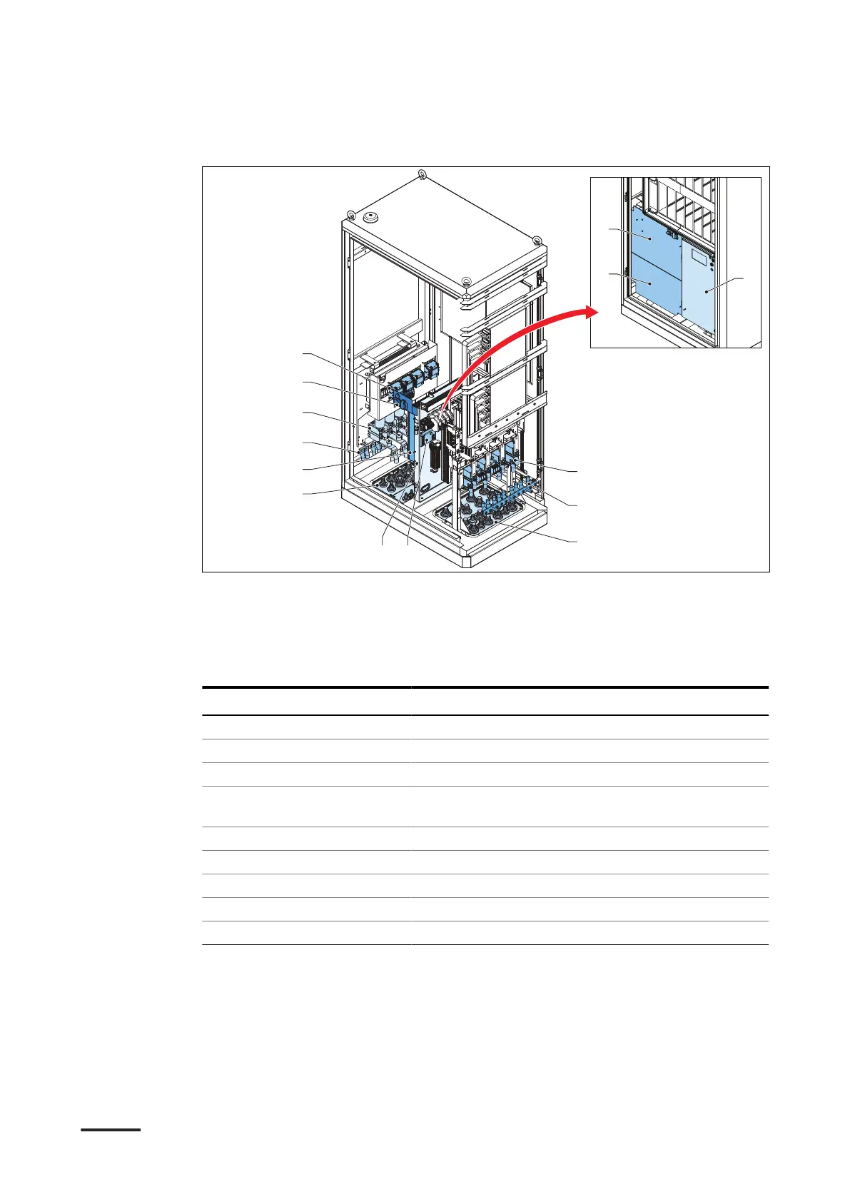
3.3.3 Power cabinet, inside
A AC contactor
B AC input fuses
C PE busbar
D AC plate
E Cable inlet
F DC plate
G CAN2ETH board
H DC output busbars
I DC door
J AC protection covers
K Precommissioning switch
Part Function
AC contactor To connect the AC power
AC input fuses To protect the device from a power disruption
PE busbar To connect PE cables
AC plate To connect the AC and the precommissioning ca-
bles
Cable inlet Opening for the cables
DC plate To connect the interlock and LED cables
CAN2ETH board To connect the Ethernet cables
DC output busbars To connect the DC output power cables
Precommissioning switch To start or stop the precommissioning mode
Description
HVC 200/300/360-EN | 002 23