7.Wiring diagram
The operations to carry out for the correct connection and wiring of the control unit and the I/O modules
are described in this section.
7.1.Control unit
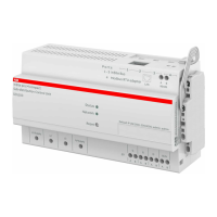
Connection of SCU100 is based on the type of electric line available.
The SCU100 includes an own power supply on L1-N. No external power supply is required.
The contacts l1, l2, l3, l4/ N are provided for connecting the external current transformer.
Installation to mains
Installation of SCU100 to mains shall include a switch or a circuit breaker for the connection to them.
The switch or circuit breaker must be suitably located and easily reachable and must be marked as the
disconnecting device for the SCU100.
Disconnection from mains or connection to mains
Switch off circuit breaker or switch before disconnecting from the mains supply or connecting to the
mains supply. Same applies for all other connections (L1, L2, L3, N).
0.56 - 0.8 Nm
4lb-in
0.56 - 0.8 Nm
4lb-in
0.56 - 0.8 Nm
4lb-in
10 mm 0.39 in
Ø max. 2.5 mm
2
1xAWG 24-14
Attention: The installation and the cabling of the device must be carried out by qualified personnel.
Danger of electrocution, burning and electric arc. Use the personal protection devices suitable to adhere
to the current regulations governing electrical safety. Prior to carrying out any connections check the
sectioning of the electric supply with the voltage detection device.
SCU100 INSITE PRO M COMPACT USER MANUAL 27

 Loading...