NoteAction
xx2200000539
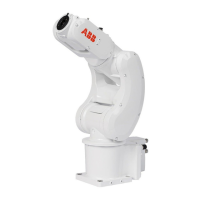
Carefully align the wrist unit to the axis 3-4 as-
sembly unit by the screw holes.
3
Flange socket head screw, M3x16
12.9 Lafre 2C2B/FC6.9+PrO-
COat111, 3HAB3412-316 (8 pcs)
Refit the wrist unit.4
Tightening torque: 1.2 Nm
xx2200000047
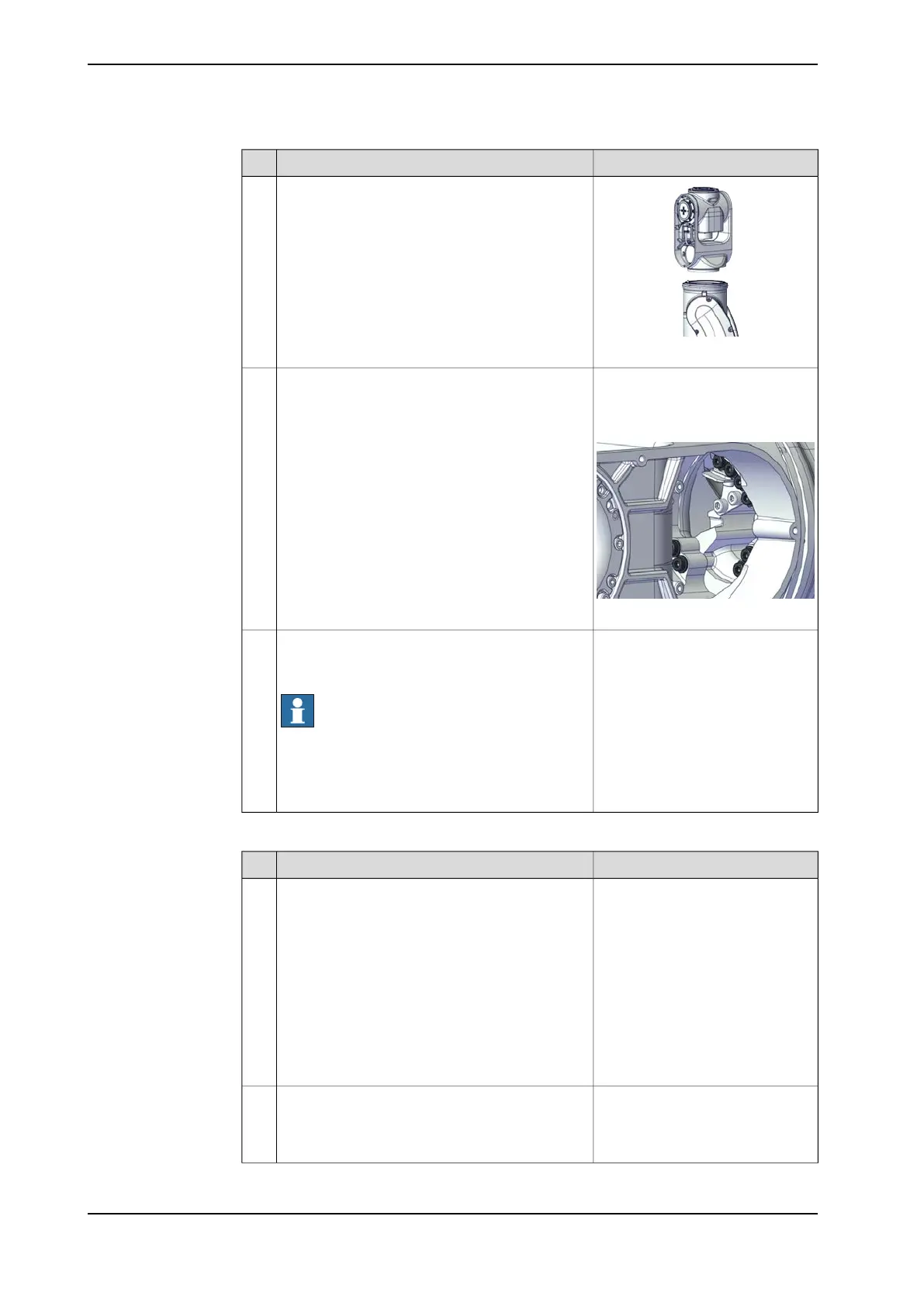
Connect the power supply to axis-3 motor and
release the axis-3 brake to move the axis 3 to zero
position. Then, disconnect the power supply.
Note
The robot is not connected to the controller during
replacement, power must be supplied to the con-
nector R1.MP according to the section Supplying
power to connector R1.MP on page 56.
5
Refitting the axis-5 motor
NoteAction
Arrange the cable package as follows:
• Cablings out from the process hub
- air hoses
- CP/CS cabling (connector R2.C1)
- axis-5 motor cablings (connectors MP5
and FB5)
• Cablings out from the right side of wrist
unit (facing the tool flange)
- axis-6 motor cablings (connectors MP6
and FB6)
- pressure relief pipe connector
1
Check that:
• all assembly surfaces are clean and without
damages
• the motor is clean and undamaged.
2
Continues on next page
236 Product manual - IRB 1010
3HAC081964-001 Revision: B
© Copyright 2022 ABB. All rights reserved.
5 Repair
5.4.4 Replacing the wrist unit
Continued