4 Repair
4.3.1. Replacement of cable harness
1193HAC026660-001 Revision: C
© Copyright 2006-2008 ABB. All rights reserved.
Refitting, cable harness in frame and base
The procedure below details how to refit the cabling inside the frame and the base.
The cable layout is shown in the figures Illustration, cabling inside frame on page 117 and
Illustration, cabling inside base on page 118.
Action Note
1.
DANGER!
Turn off all electric power, hydraulic and
pneumatic pressure supplies to the robot!
2. Run the cables from the lower arm into the
frame.
3. Fit the cable clamp unit to the fastening plate
with two attachment screws, but do not secure
the plate to the frame yet.
Shown in the figure Illustration, cabling
inside frame on page 117.
4. Run the cabling down to the base. Pull it out at
the rear of the base.
5. Connect all the connectors inside the frame
and secure all plates and cable brackets inside
the frame with attachment screws and nuts.
Shown in the figure Illustration, cabling
inside frame on page 117.
6. In the base, secure the cabling to the bottom
fastening plate:
• fit the cable clamp unit with two
attachment screws (M6).
• fit the separate cables with clamps and
hexagon nuts.
Shown in the figure Illustration, cabling
inside base on page 118.
7. Refit the SMB unit to the fastening plate with
hexagon nuts.
Shown in the figure Illustration, cabling
inside base on page 118.
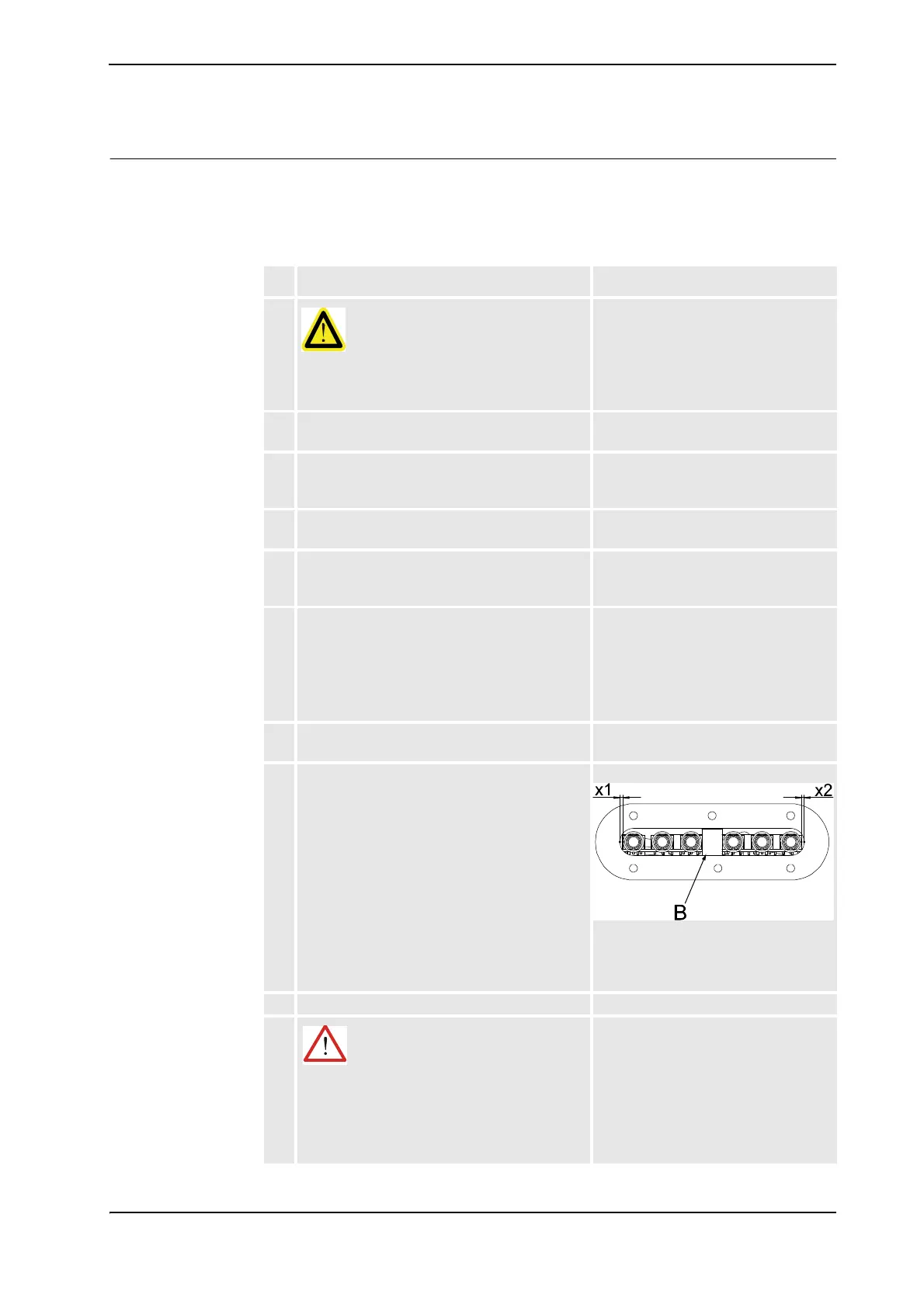
8. Refit the centering piece (B) to the push button
unit in order to align it vertically.
Also make sure that the unit is correctly aligned
sideways: the measurements x1 and x2 in the
figure to the right should not differ more than 1
mm from each other!
xx0600002777
Art. no. for the centering piece is
specified in Required equipment on
page 112.
9. Refit the push button guard to the robot base.
10.
WARNING!
Before continuing any service work, please
observe the safety information in section
WARNING - The brake release buttons may be
jammed after service work on page 34!
Continued
Continues on next page

 Loading...


