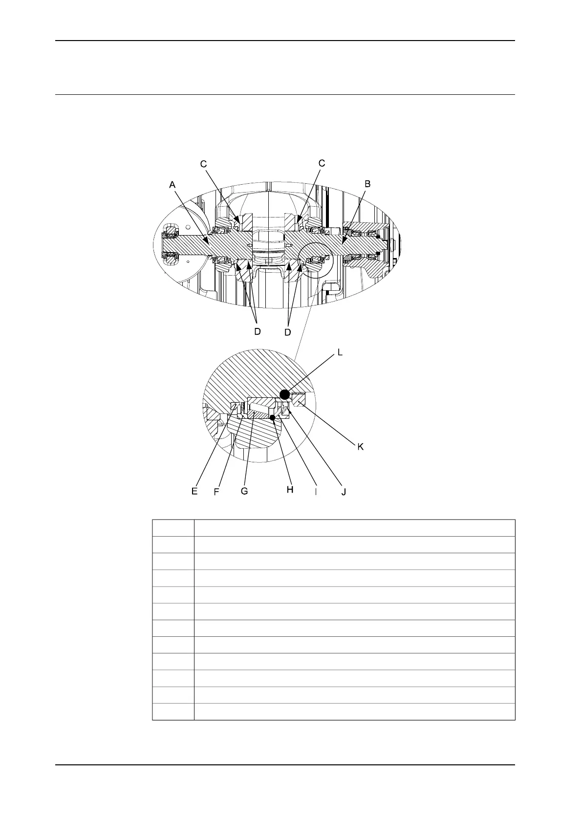
View of the assembly of the upper arm components
Shown below is a cut away view of how the upper arm is fitted to the lower arm
(seen from above). The letters are being referred to in the following step by step
procedures.
xx0600002692
Shaft, axis 2A
Shaft, axis 3B
Set screw, cup point (M10 x 20)C
Lubricant paste (Molycote 1000)D
Sealing ring (V-ring)E
Sealing ringF
Taper roller bearingG
O-ringH
Sealing ringI
Sealing assemblyJ
Lock nut (KM12)K
O-ring (Di = 54.2 mm, t = 5.7 mm)L
Continues on next page
192 Product manual - IRB 660
3HAC025755-001 Revision: W
© Copyright 2006-2020 ABB. All rights reserved.
4 Repair
4.4.3 Replacement of upper arm
Continued