NoteAction
Art. no. is specified in Required
equipment on page 221.
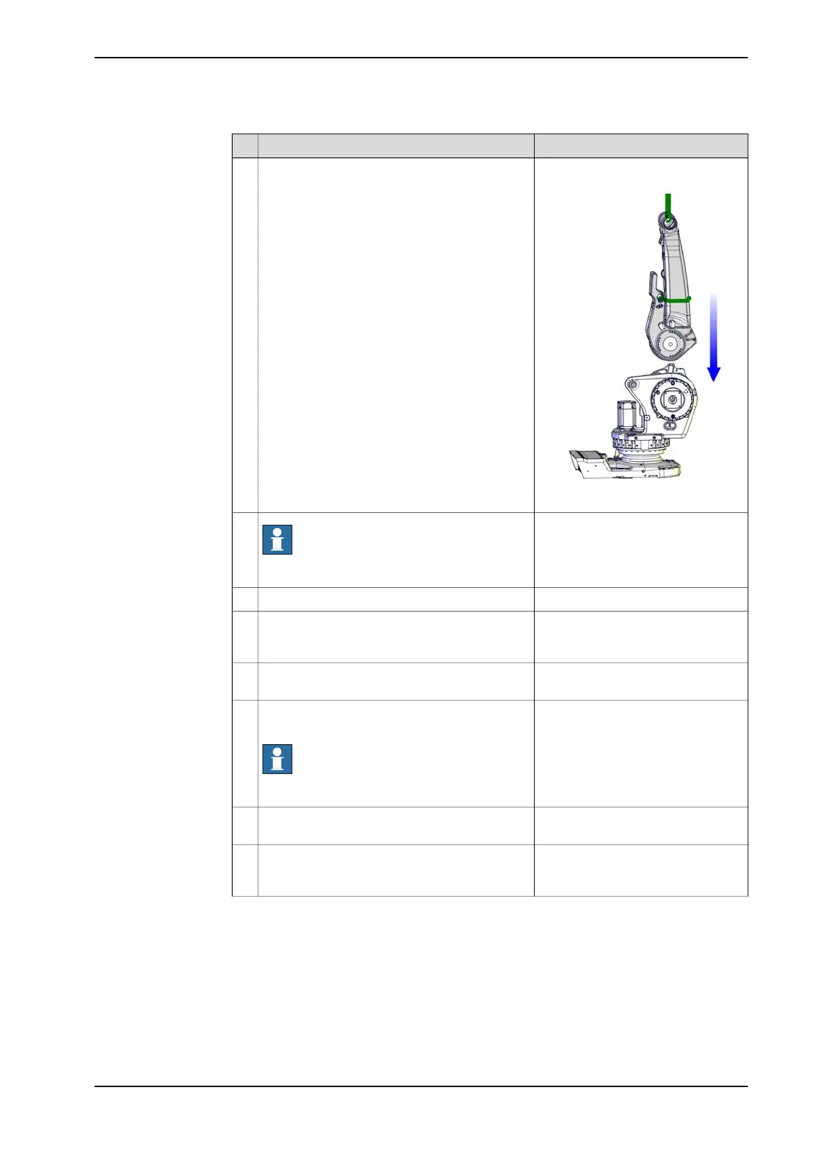
xx1000001370
Put the lower arm in its mounting position.
If the hole pattern needs to be adjusted, use a
crank to move the gears in order to find the cor-
rect hole pattern.
5
Note
Refit the axis 2 side first!
6
Verify that the sealings are still in place.7
Tightening torque M16: 300 NmRefit all screws (both M12 and M16) and wash-
ers, that are possible to fit at this stage, on the
axis 2 side.
8
Tightening torque M12: 120 Nm
Push the parallel arm against the axis 3 side with
the help of an iron bar or similar.
9
Tightening torque M12: 120 NmRefit all screws and washers, that are possible
to fit, on the axis 3 side.
Note
The axis 3 side has no M16 screws!
10
Remove the guide sleeves and secure two
screws more.
11
Change the position of the lower arm in order to
reach the remaining attachment holes, and fit
the remaining screws.
12
Continues on next page
Product manual - IRB 660 227
3HAC025755-001 Revision: W
© Copyright 2006-2020 ABB. All rights reserved.
4 Repair
4.4.8 Replacing the complete lower arm
Continued