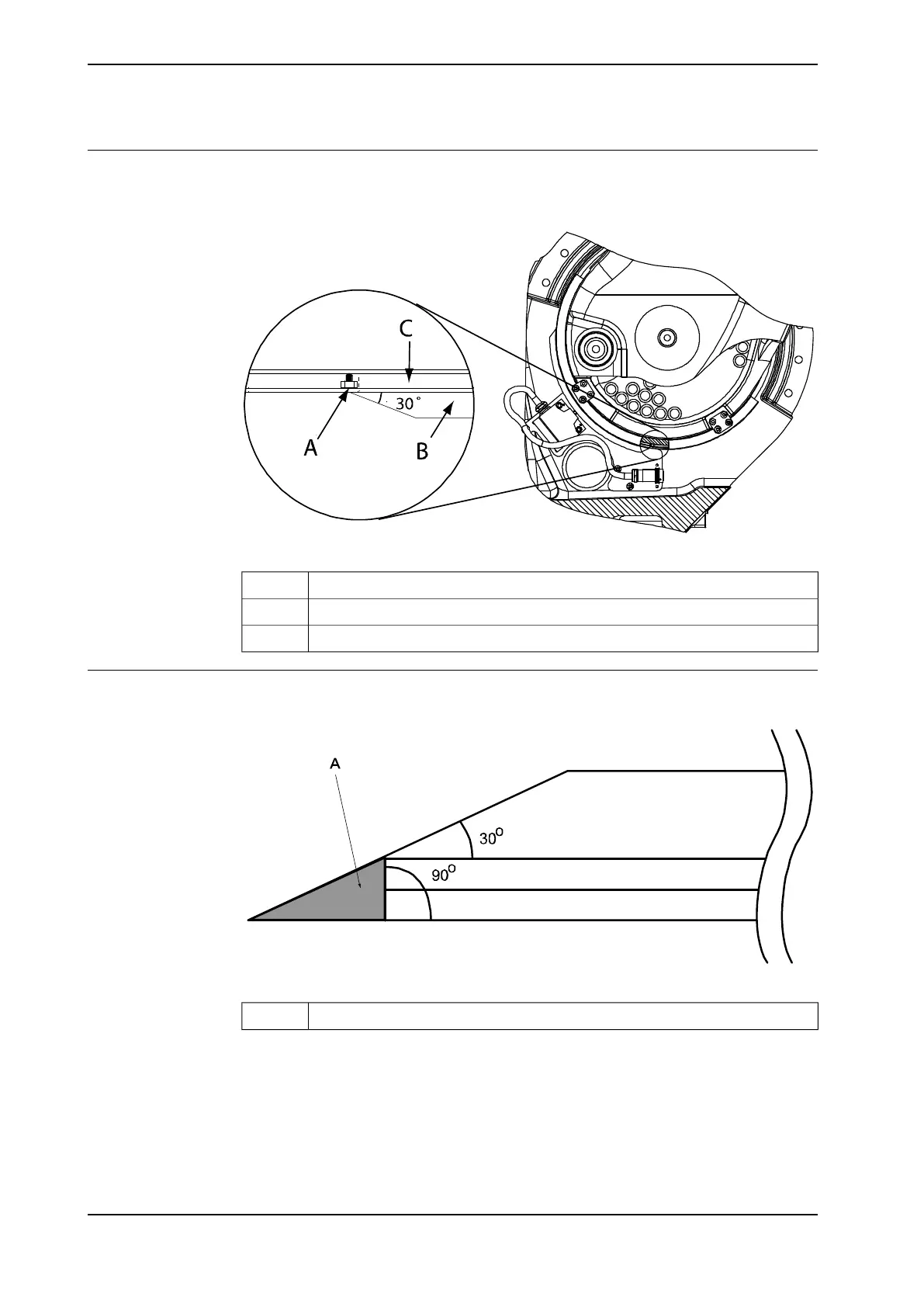
Illustration, adjust and secure cams
The illustration below shows how to adjust and secure the position switch cams
and profiles.
xx0100000113
Cam stop, M5 nut and M5 x 6 set screwA
Adjustable camB
ProfileC
Illustration, cutting the cam
The illustration below shows how to cut the position switch cam.
xx0100000114
Remove the gray sectionA
86 Product manual - IRB 660
3HAC025755-001 Revision: W
© Copyright 2006-2020 ABB. All rights reserved.
2 Installation and commissioning
2.4.4 Installation of position switch, axis 1 (option)
Continued