16
AUTOMATIC CONTROL UNIT, OMD100
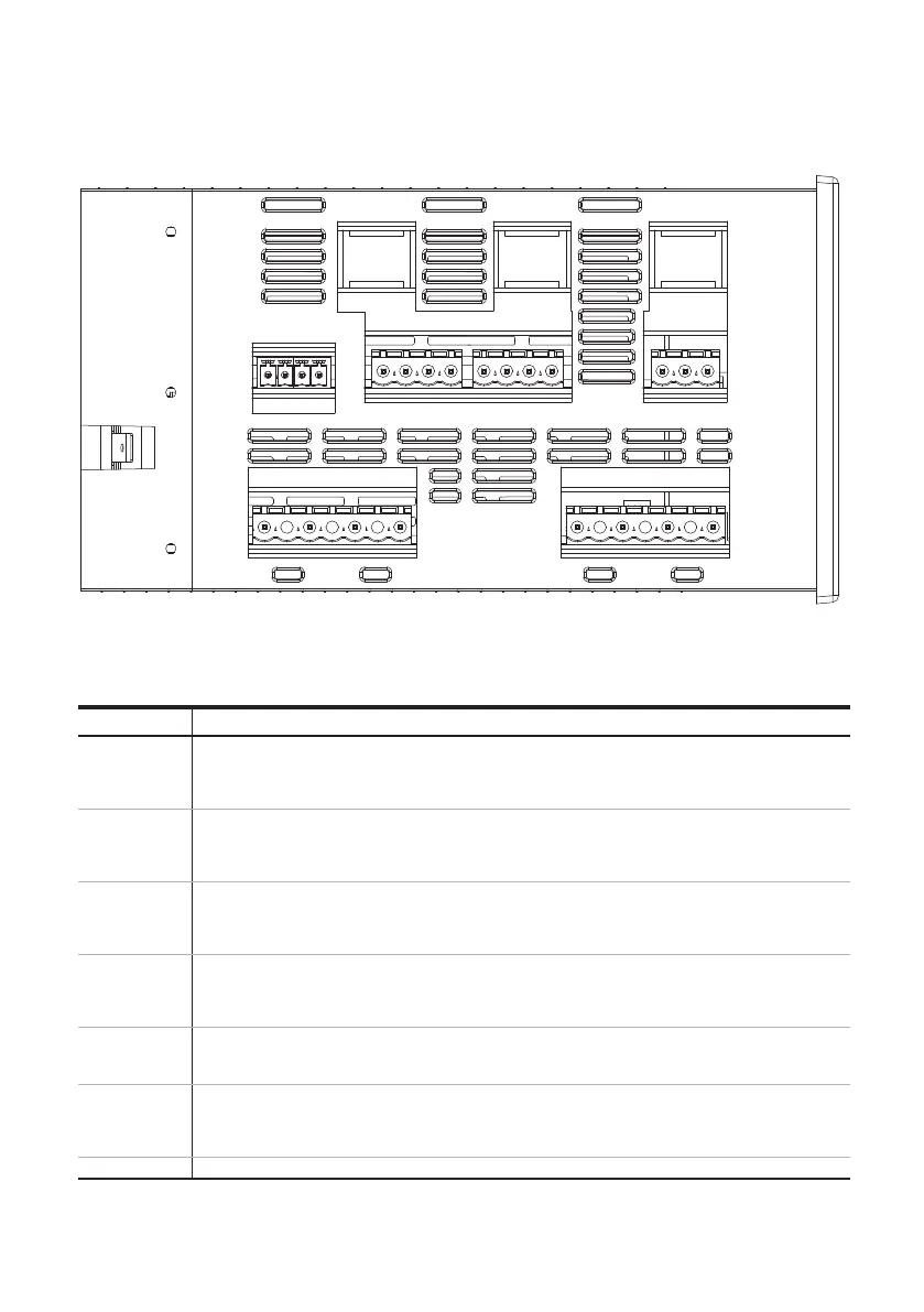
5.2.3 Connectors, OMD100
Table 5.1 Connectors OMD 100
Figure 5.3 Connectors, OMD100
Connector Description
X11:1
X11:2
X11:3
X11:4
Supply I: L1
Supply I: L2
Supply I: L3
Supply I: N
X12:1
X12:2
X12:3
X12:4
Supply II: L1
Supply II: L2
Supply II: L3
Supply II: N
X21:1
X21:2
X21:3
X21:4
Voltage supply from motor operator OME_ Common
Output to close switch I NO
Output to close switch II NO
Voltage supply from motor operator OME_ Common
X22:1
X22:2
X22:3
X22:4
Voltage supply from motor operator OME_ Common
Output to open switch I and switch II NO
Reserved
Reserved
X24:1
X24:2
X24:3
Output to signal OK (no alarm)
Common
Output to signal Alarm
X31:1
X31:2
X31:3
X31:4
Manual / Alarm input from handle
Status of switch I auxiliary contact
Status of switch II auxiliary contact
Voltage supply from the automatic control unit OMD100
X61 Equipment earth
KA00287
2 1
2 1 2 1
1 2 3 4
1 2 3 4 1 2 3 4
1 2 3 4
1 2 3 4
1 2 3
X26
X27 X28
X31
X21 X22
X11
X24
X12
X61