2
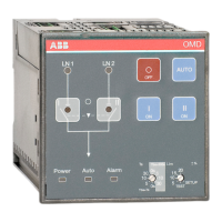
AUTOMATIC CONTROL UNIT, OMD100
—
Table of contents
1. Introduction 4
1.1 Use of symbols 4
1.2 Explanations of abbreviations and terms 4
2. Product overview 5
2.1 Typical applications 6
3. Description 7
3.1 OMD100 switching sequence 7
3.1.1 Line 1 priority 7
3.1.2 No line priority 8
3.1.3 Manual back switching 9
4. Installation 10
4.1 Dimensional drawings 10
4.2 Mounting 11
4.2.1 Automatic control unit OMD100, door mounting 11
4.2.2 Automatic control unit OMD100, DIN-rail mounting 12
5. Connecting 13
5.1 Power circuit 13
5.2 Control circuit 14
5.2.1 Control circuit diagram OMD100 with motorized
OTM40...125_CMA_ 14
5.2.2 Control circuit diagram OMD100 with motorized
OTM160...2500_CM_ 15
5.2.3 Connectors, OMD100 16
5.2.4 OMD100 outputs 17
5.2.5 OMD100 inputs 17
6. Operating 18
6.1 Automatic control unit in Manual Mode 18 – 20
6.2 Automatic control unit in Automatic Mode 20
6.3 Selection of delay time, voltage threshold and
TEST function 21 – 22
6.4 Operating modes 23
6.4.1 Operating modes in OMD100 23
6.4.2 Choice of Operating mode in OMD100 24 – 26