17
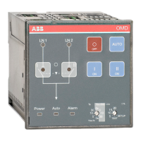
AUTOMATIC CONTROL UNIT, OMD100
AUTOMATIC CONTROL UNIT, OMD100
5.2.4 OMD100 outputs
5.2.4.1 Opening/closing command to change-over switches, X21 (DO1-DO3)
These outputs command the change-over switch to open and close Switch I or Switch II.
To guarantee the highest-level safety OMD100 monitors the correct operation of the change-over
switch after a command has been sent. If the feedback of the switch status is not received within 3
seconds of the sending of the command, the device considers it as a failed command and operates
as follows:
An alarm is generated: DO6 activate.
Alarm LED switches on.
Alarm is set off by pushing the AUTO key. After that the device is always in the Manual Mode to
prevent unwanted operation of the change-over switch.
Exactly the same operations are performed on the secondary line (LN2-Switch II) during the back
switching sequence.
5.2.4.2 Alarm signaling, X24 (DO6)
When the relay contact Alarm (X24:3) is open and contact OK (X24:1) is closed, the automatic
transfer logic is enabled. If the relay contact Alarm (X24:3) is closed and the contact OK (X24:1) is
open the automatic transfer logic is disabled and an alarm is active.
5.2.5 OMD100 inputs
5.2.5.1 Switch status input, X31:2 (DI1), X31:3 (DI2)
These two inputs are connected to change-over switch auxiliary contacts. Input X31:2 (DI1) is
connected to LN1-Switch I and input X31:3 (DI2) is connected to LN2-Switch II (Switch I / II open
= input inactive, Switch I / II closed = input active). Auxiliary contacts are in-built in motorized
OTM40…125_CMA_. If OMD100 is used with motorized OTM160…2500_CM_, use always type
OA1G10 auxiliary contacts with DI1 and DI2. See the wiring diagrams on Figure 5.1 and Figure 5.2.
5.2.5.2 Force manual, X31:1 (DI3)
When the handle is attached this input is closed and OMD100 is forced to Manual Mode. To set the
OMD100 back to the Automatic Mode the handle must be removed and the AUTO key pushed (Auto
LED is ON).