28
AUTOMATIC CONTROL UNIT, OMD100
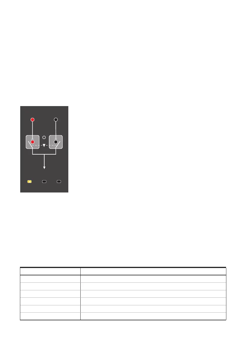
7.1.2 LEDs
Figure 7.3 LEDs on OMD100
Line 1 status (LN1)
A red LN 1 LED signals the status of the line LN 1. Line status and indication is explained in the
Table 7.1.
Line 2 status (LN2)
A red LN 2 LED signals the status of the line LN 2. Line status and indication is explained in the
Table 7.1.
Line Status LED Indication
Voltage OK ON
No voltage OFF
Overvoltage Fast blinking (5 Hz, 50 % ON / 50 % OFF)
Undervoltage Blinking (1 Hz, 50 % ON / 50 % OFF)
Invalid frequency Blinking (1 Hz, 90 % ON / 10 % OFF)
Unbalance Blinking (1Hz, 10 % ON / 90 % OFF)
Table 7.1 Line status indication
I II
Power
Auto Alarm
LN 1 LN 2
KA00293
I key
Setting in manual mode the motorized change-over switch OTM_C to position I, when the I-switch
will be in the ON position and the II-switch will be in the OFF position.
II key
Setting in manual mode the motorized change-over switch OTM_C to position II, when the II-switch
will be in the ON position and the I-switch will be in the OFF position.