Electrical connections
44 - EN FEX300, FEX500 CI/FEX300/FEX500-EN
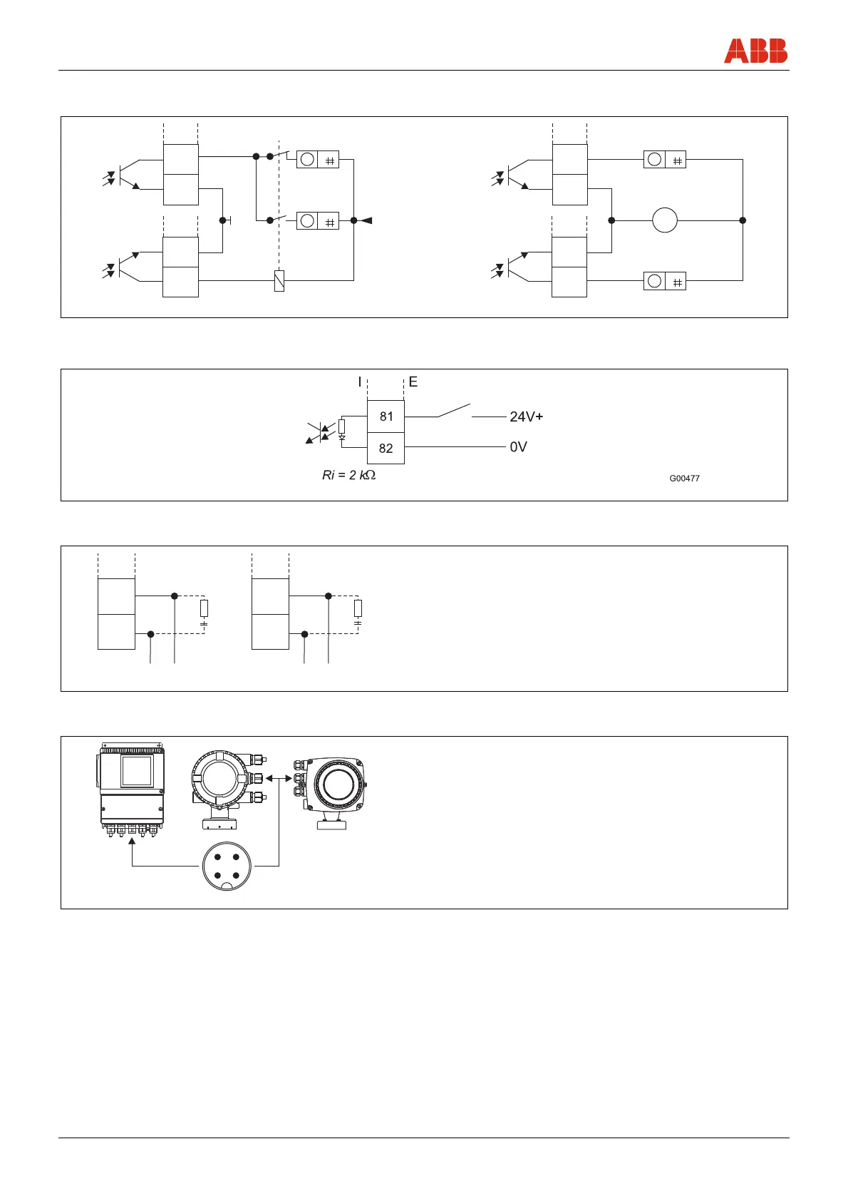
Digital outputs DO1 and DO2, separate forward and reverse
pulses
Digital outputs DO1 and DO2, separate forward and reverse
pulses (alternative connection)
G00791
24V+
I E
51
52
41
42
24V
I E
51
52
41
42
V
+
-
I = internal, E = external
Fig. 43
Digital input for external output switch-off or external totalizer reset
I = internal, E = external
Fig. 44
PROFIBUS PA and FOUNDATION fieldbus
G00248
2
FF-
FF+
R
C
1
97
PA-
R
C
PA+
98
97
98
I EI E
The resistance R and condenser C form the bus termination. They must
be installed when the device is connected to the end of the entire bus
cable.
R = 100 Ω; C = 1 µF
1 PROFIBUS PA
2 FOUNDATION fieldbus
I = internal, E = external
Fig. 45
Connection via M12 plug (only for PROFIBUS PA in non-hazardous areas)
G01003-01
12
3
4
Pin assignment
(Front view showing pin insert and pins)
PIN 1 = PA+
PIN 2 = nc
PIN 3 = PA-
PIN 4 = shield
Fig. 46