3.10.3.1 Functional diagrams for protection
The functional diagrams describe the IEDs protection functionality in detail and
according to the factory set default connections.
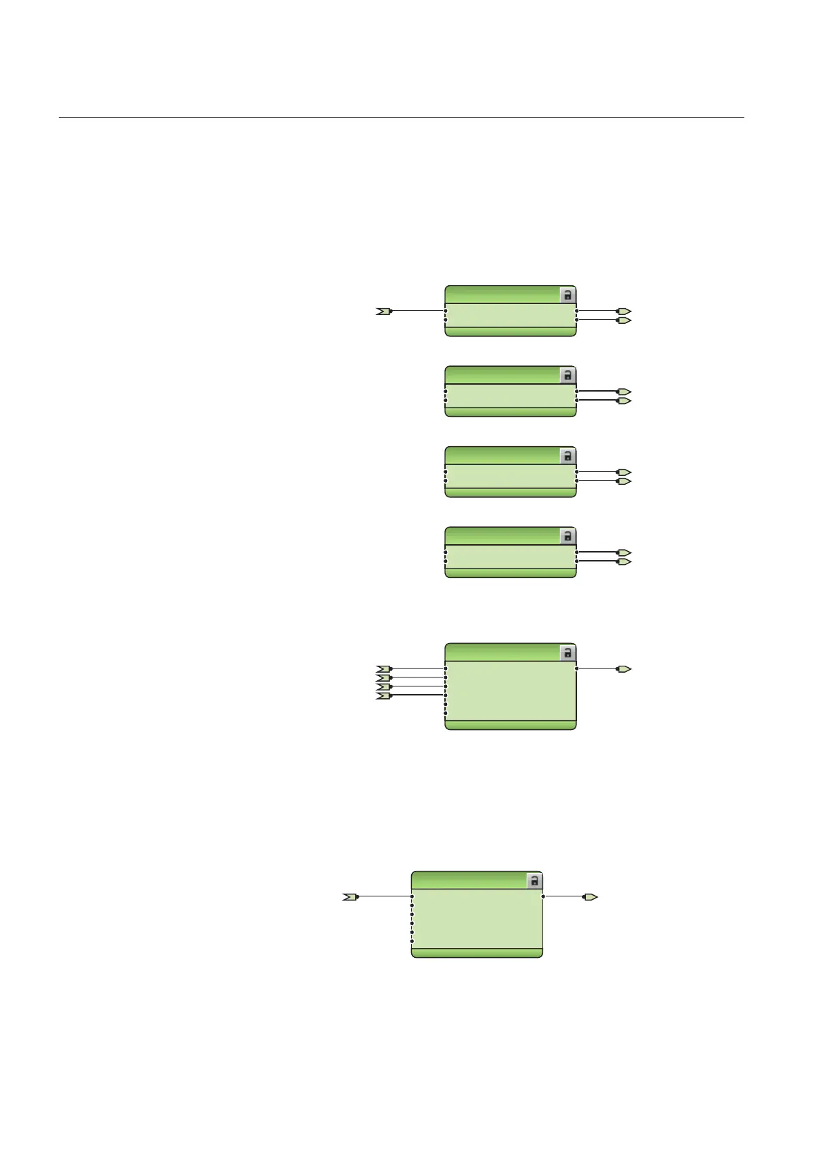
Four non-directional overcurrent stages are offered for overcurrent and short-circuit
protection. Three-phase non-directional overcurrent protection, instantaneous stage,
PHIPTOC1 can be blocked by energizing the binary input X120:BI1.
PHIPTOC1
BLOCK
ENA_MULT
OPERATE
START
PHLPTOC1
BLOCK
ENA_MULT
OPERATE
START
PHHPTOC1
BLOCK
ENA_MULT
OPERATE
START
PHHPTOC2
BLOCK
ENA_MULT
OPERATE
START
OR6
B1
B2
B3
B4
B5
B6
O
PHIPTOC1_OPERATE
PHIPTOC1_OPERATE
PHLPTOC1_OPERATE
PHLPTOC1_OPERATE
PHHPTOC1_OPERATE
PHHPTOC1_OPERATE
PHHPTOC2_OPERATE
PHHPTOC2_OPERATE
PHLPTOC1_START
PHHPTOC1_START
PHHPTOC2_START
PHIPTOC1_START
X120_BI1_EXT_OC_BLOCKING
PHxPTOC_OPERATE
GUID-4418FE50-A21E-4DA3-B13C-97D408EB4CFA V1 EN
Figure 334: Overcurrent protection function
The upstream blocking from the start of the second high stage of three-phase non-
directional overcurrent protection PHHPTOC2 is connected to the binary output
X110:SO1. This output can be used for sending a blocking signal to the relevant
overcurrent protection stage of the IED at the infeeding bay.
OR6
B1
B2
B3
B4
B5
B6
O
UPSTEAM_OC_BLOCKINGPHHPTOC2_START
GUID-9B85F4BF-82D4-4867-B89B-1E73F145341C V1 EN
Figure 335: Upstream blocking logic
Section 3 1MRS756378 S
REF615 standard configurations
232 REF615
Application Manual