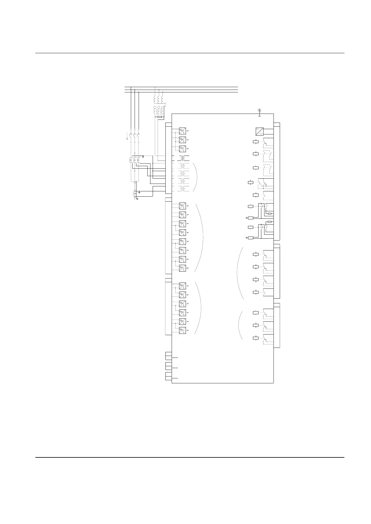
REF615
X13
Light sensor input 1
1)
X14
Light sensor input 2
1)
X15
Light sensor input 3
1)
1) Optional
X130 module optional in REF615 conf B
2) The IED features an automatic short-circuit
mechanism in the CT connector when plug-in
unit is detached
3) REF615 conf B: BIO0005 module (8BI+4BO)
Alternative module BIO0007 (8BI+3HSO)
4) REF615 conf B: BIO0006 module (6BI+3BO)
Alternative module RTD0001 (6RTD+2mA)
16
17
19
18
X100
6
7
8
9
10
11
12
13
15
14
2
1
3
4
5
22
21
23
24
SO2
TCS2
PO4
SO1
TCS1
PO3
PO2
PO1
IRF
+
-
Uaux
20
X130
1
2
3
4
5
6
BI 4
BI 3
BI 2
BI 1
BI 6
BI 5
8
9
7
X130
12
10
11
15
13
14
18
16
17
SO3
SO2
SO1
1)
4)
L1
L2
L3
da dn
S1
S2
P1
P2
P2
P1
S1
S2
X110
3
4
5
6
7
8
9
10
BI 6
BI 5
BI 4
BI 3
BI 2
BI 8
BI 7
12
13
11
BI 1
1
2
X110
16
14
15
19
17
18
22
20
21
SO3
SO2
SO1
23
SO4
24
A
N
2)
Positive
Current
Direction
X120
1
2
3
4
5
6
7
8
9
10
11
12
13
14
Io
IL1
IL2
BI 3
BI 2
BI 1
Uo
IL3
1/5A
N
1/5A
N
1/5A
N
1/5A
N
60 -
N
210V
3)
3)
4)
1)